So the Fogger v2 has turned into a superb and currently favorite setup for me, and I wanted to share a few of the things I did along the way to make it perform the best it can, as well as a few tips/warnings and a bunch of pics.


This setup is running 3mm Ekowool, a .9 ohm 28g coil and is sitting on an 18350 8 diagrams mod.
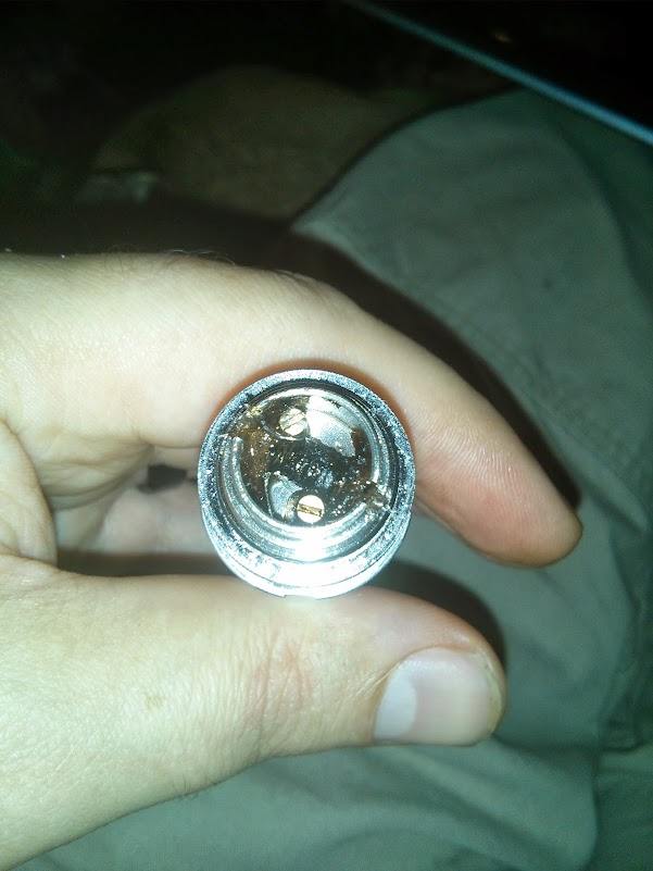
Other than the learning curve on the builds, the biggest limiting point on the Fogger v2 is the air flow. Here's the innards of the air flow control as they come:

The red circle shows the air flow tube limitation as it comes. This is the part that really causes the Fogger v2 to have a tight draw.

Number 1 shows the air flow tube cut off. This tube is thin enough to be broken off with a sturdy set of pliers. It provides no conductivity, only air restriction. There is also an insulator which the air tube normally fits into when pressing up into the center hole seen in number 2 this also should be removed. Number 3 shows the insulator around the positive screw post, more on that later.
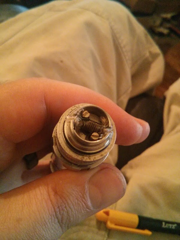
Clearing out the air path, immediately makes this mod a contender, and can be done with a simple wire cutter or even broken off with a pliers.

For those that just need that extra air, it can be pushed a bit further with a 1/16th drill bit opening the 3 external holes a bit more and giving more range for the air control. I don't feel this is necessary, but if you have the tools you can feel the air increase. The compromise is less vacuum in the atomizer chamber so your wick building has to be even better. You may find slower wicks are helped by dialing the air back down with the air flow, if you decide to open up these holes.
More details in the next post.
This setup is running 3mm Ekowool, a .9 ohm 28g coil and is sitting on an 18350 8 diagrams mod.
Other than the learning curve on the builds, the biggest limiting point on the Fogger v2 is the air flow. Here's the innards of the air flow control as they come:
The red circle shows the air flow tube limitation as it comes. This is the part that really causes the Fogger v2 to have a tight draw.
Number 1 shows the air flow tube cut off. This tube is thin enough to be broken off with a sturdy set of pliers. It provides no conductivity, only air restriction. There is also an insulator which the air tube normally fits into when pressing up into the center hole seen in number 2 this also should be removed. Number 3 shows the insulator around the positive screw post, more on that later.
Clearing out the air path, immediately makes this mod a contender, and can be done with a simple wire cutter or even broken off with a pliers.
For those that just need that extra air, it can be pushed a bit further with a 1/16th drill bit opening the 3 external holes a bit more and giving more range for the air control. I don't feel this is necessary, but if you have the tools you can feel the air increase. The compromise is less vacuum in the atomizer chamber so your wick building has to be even better. You may find slower wicks are helped by dialing the air back down with the air flow, if you decide to open up these holes.
More details in the next post.


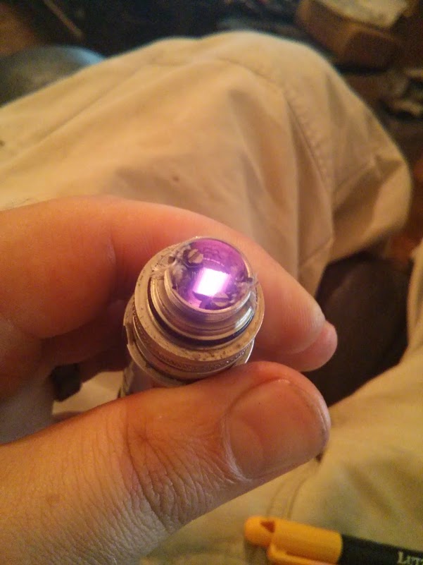
") clic pic for video.
clic pic for video.