
Yes, but it would be nice of Yihi to make a PDF Wire diagram for this chip, like Evolv does with theirs.
You are using an out of date browser. It may not display this or other websites correctly.
You should upgrade or use an alternative browser.
You should upgrade or use an alternative browser.
The YiHi SX350 35W Chip at Varitube
- Thread starter Onedesign1
- Start date
- th_trl_thread_readers 0
- Status
- Not open for further replies.
COME ON............ With what is there? You need a wiring diagram? I do NOT mean to be demeaning in anyway, but, IF you need a wiring diagram for THAT, should you be really be building that? Or possibly calling in a friend who has electronics training, and will be able to tell at a glimpse what they are dealing with. Have them guide u through a couple. Nothing wrong with that. I've done it, I expect most of us have done just that a time or three. I have FINALLY had to realize in myself, that I am TOO old, to build some of these. I had one of the early ones, we had to solder the charging boards on ourselves. It was TOO small. I could NOT see it well enough any more, and my hands shook like a tree in a hurricane. I had to call "HELP". And, I did. And, I did a fair bit of Graduate work in several of the Sciences. THAT, is embarrassing, at least to me. SO NOW, a young Hot shot (he thinks) has it to "straighten out" for me. We ALL must ask for help at times. Hopefully, before it is too late, and you let all that pretty blue smoke out that makes it work so well.
Remember TruckerMSA, NO teasing, NO "I'm bettter than you" none of that, just a bit of advice from someone who has been where you are. And, apparently, am BACK, in a sense.
Remember TruckerMSA, NO teasing, NO "I'm bettter than you" none of that, just a bit of advice from someone who has been where you are. And, apparently, am BACK, in a sense.
Last edited:
I got my chips yesterday I only made sure they fired up, they did. I went to work came back home and upgraded both to 35watts with no instructions whatsoever, next I found where the 510 connections are within 5 minutes of inspecting the board but yes for someone with limited electronics background it can be a nightmare.
But then if you don't have much experience Just ask don't blame the makers or even the seller "Remember the seller is not at fault, he is only selling a product".
But then if you don't have much experience Just ask don't blame the makers or even the seller "Remember the seller is not at fault, he is only selling a product".
Last edited:
I agree with both sides. But it would be nice to have something to point inexperienced builders to, not to mention professional of Yihi.
Last edited:
I thought I did that..... I said, for him to FIND a friend who had some solid electronics experience, and get them to help through a couple of those builds. But, Make certain they ARE solid when IT comes to electronics. A LOT of people SAY they are. DOn't let the proof be In YOUR pudding.. ") Everybody has friends, some are very likely to be good at electronics. Many are these days. Grab one, have him/her, come have a look, and see what they see.... There has GOT to be someone close, who can HANDS ON guide you through a build. I prefer guiding someone toward a PERSON, not a .pdf. They are much more helpful, especially not knowing the level of competance of the person seeking help.
Everybody has friends, some are very likely to be good at electronics. Many are these days. Grab one, have him/her, come have a look, and see what they see.... There has GOT to be someone close, who can HANDS ON guide you through a build. I prefer guiding someone toward a PERSON, not a .pdf. They are much more helpful, especially not knowing the level of competance of the person seeking help.
Everybody has friends, some are very likely to be good at electronics. Many are these days. Grab one, have him/her, come have a look, and see what they see.... There has GOT to be someone close, who can HANDS ON guide you through a build. I prefer guiding someone toward a PERSON, not a .pdf. They are much more helpful, especially not knowing the level of competance of the person seeking help.When I got mine the usb wasn't soldered on the board (didn't get it from Varitube), but I also got two papers. One of the below and one with some dimensions and showed where the usb wires need to be soldered to the board. My copy is all folded and nasty and I have been looking for a digital copy to share.

I am asking YiHi for 2 things:
1) Wiring schematic that I can put on the site for download or post somewhere
2) CAD drawings for the board so everybody can get dimensions for planning purposes
or whatever they are willing to provide I suppose!
Will of course keep everyone posted on progress here
1) Wiring schematic that I can put on the site for download or post somewhere
2) CAD drawings for the board so everybody can get dimensions for planning purposes
or whatever they are willing to provide I suppose!
Will of course keep everyone posted on progress here
Well, I never said I needed the diagram but I do agree with what everyone has said. But my boards did not come with that drawing. The very least it should have, for the inexperience modders and instructions on the menu system. It's just professional that way.
Well, I never said I needed the diagram but I do agree with what everyone has said. But my boards did not come with that drawing. The very least it should have, for the inexperience modders and instructions on the menu system. It's just professional that way.
The early boards same have are version 1.2 and that's the ones with the unsoldered usb, this are the Rev 1.3 and the usb is soldered but exactly the same board.
these boards are awesome but they are a bit large and deep, a spec sheet with dimensions would be very helpful for anyone considering using this board I guess. also was wondering if there is any chance of flipping the screen through software eventually, that and being able to flap the screen open instead of it being glued in place on top of the board would add some flexibility to the install but then again that might open up the possibility of more guys having ribbon cable breakage too. now it's solid and secure but less flexible as far as mod design. also just an opinion but personally I would rather have the board without all the leads pre soldered and then epoxied... either that or leave very long leads, I hate to have to use a soldered splice in just a few inches of wire... pre wired may help some I guess but hinder others... overall I really like this board and hope it does keep up with demand as far as availability
how does it look from your end? does it look like they are going to be able to keep up with production so these are always available or do you think thy are going to sell out and then keep having to play catch up?
how does it look from your end? does it look like they are going to be able to keep up with production so these are always available or do you think thy are going to sell out and then keep having to play catch up?
Display....I dunno...I have had far too many zmax units with torn ribbons and they are attached to a foam platform....usually damaged during assembly but pass test and work for awhile and then nothing.
The USB I can get unsoldered but its a fine solder point and closely spaced and not everyone can board solder well. I prefer to have as little need to touch the board as possible.
As far as supply so far so good. They are not quick in the shop but they seem to be keeping up. I don't think it'll be an issue.
these boards are awesome but they are a bit large and deep, a spec sheet with dimensions would be very helpful for anyone considering using this board I guess. also was wondering if there is any chance of flipping the screen through software eventually, that and being able to flap the screen open instead of it being glued in place on top of the board would add some flexibility to the install but then again that might open up the possibility of more guys having ribbon cable breakage too. now it's solid and secure but less flexible as far as mod design. also just an opinion but personally I would rather have the board without all the leads pre soldered and then epoxied... either that or leave very long leads, I hate to have to use a soldered splice in just a few inches of wire... pre wired may help some I guess but hinder others... overall I really like this board and hope it does keep up with demand as far as availability
how does it look from your end? does it look like they are going to be able to keep up with production so these are always available or do you think thy are going to sell out and then keep having to play catch up?
I have noticed the boards are well coated/protected with a varnish like material from the factory. So careful cleaning around any points you would be souldering to is needed. The potting and the fact that the screen is well attached I like. This reduces the possibilty of damage during assembly or vibration during use. I recomend a good souldering iron with a 1/32" chisel tip .032" 60/40 soulder. I didnt have my good iron when I worked on my board and it was cumbersome. Keep your iron clean and wet with solder.
Hey DrBeaker....thanks for stopping by! Good advice!
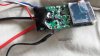
I just received my new SX-350 board. I pulled it out of the package and noticed the strain relief added to the USB board and it is pre soldered. Very nice touch! and I see that the factory soldered the wires coming from the back side of the board that's the opposite side of the lcd screen. That is not the way I soldered my first unit. Maybe that is why I found it to be cumbersome to solder. Anyway you wont have to worry about it with the new boards its done for you.
Right out of the package I plugged it into my computer running win7 installed the driver selected the file and clicked the upgrade and it was done in about a minute.
Now I will be mounting it into my Radio Shack plastic box with a Sony VT5 30Amp battery and Omega RBA .3ohm coil and see how it works.
Awesome DrBreaker, be sure to post your results
How is this for results. 35Watts

4.08v .4ohms 35W
4.08v .4ohms 35W
Thanks for sharing the work Dr! Hows it running for you at those settings?
alright time for you show me yours and I show you mine
This is what I threw together yeterday...I don't know why the pics rotated other than its from my phone


This is what I threw together yeterday...I don't know why the pics rotated other than its from my phone
- Status
- Not open for further replies.
Similar threads
- Replies
- 122
- Views
- 30K
- Replies
- 15
- Views
- 2K
- Locked
- Replies
- 1
- Views
- 149
Users who are viewing this thread
Total: 3 (members: 0, guests: 3)