510 Box Mod Kit

Status
Not open for further replies.

zer0ith

Ultra Member
ECF Veteran
Verified Member
Mar 28, 2011
2,261
2,061
42
Burlington, Ontario
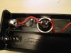
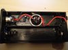
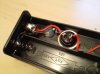
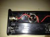
So I've just got my order of the 510 Box mod Kit. So I assembled one (according to the directions on the site), soldered everything together and placed my battery (red AW IMR 14500) in and got nothing :(
I got the multimeter out (thinking I may have a bad connection somewhere) and measured the resistance from solder joint to joint, all check out (even makes the LED glow when testing that connection).

My question to anyone that can help, are the battery's I'm using the wrong type?
 

zer0ith

Ultra Member
ECF Veteran
Verified Member
Mar 28, 2011
2,261
2,061
42
Burlington, Ontario
As long as batt is making good contact, the type shouldn't matter.
Did you check the continuance on the switch?

Prolly gonna need a pic of the insides for any real help.

Not sure what exactly you mean by continuance of the switch (unless that means measured the resistance of the switch when activated then yes it was like 0.02)

I'll try and get the pics up right now (on my computer the forum was complaining they were too large)
 

zer0ith

Ultra Member
ECF Veteran
Verified Member
Mar 28, 2011
2,261
2,061
42
Burlington, Ontario
Here we go. I did use a bit of hot glue on the led to hold it in place, as well after a soldered the wire to the middle pin of the 510 connection
 

Attachments

  • ImageUploadedByTapatalk1320289569.086857.jpg
    ImageUploadedByTapatalk1320289569.086857.jpg
    21.7 KB · Views: 43
  • ImageUploadedByTapatalk1320289612.102325.jpg
    ImageUploadedByTapatalk1320289612.102325.jpg
    21.9 KB · Views: 34
  • ImageUploadedByTapatalk1320289697.242873.jpg
    ImageUploadedByTapatalk1320289697.242873.jpg
    22.6 KB · Views: 32
  • ImageUploadedByTapatalk1320289745.486020.jpg
    ImageUploadedByTapatalk1320289745.486020.jpg
    22.1 KB · Views: 38
Last edited:

VpnDrgn

Ultra Member
ECF Veteran
Jul 21, 2010
1,310
382
Gulfport, MS.
Everything appears to be connected properly, but you mention checking resistance,
you need to be checking if connections are passing current ( continuance ).
You are checking to see if juice is getting from point A to point B ( closed circuit ),
I am pretty sure that is a different setting on meter from checking resistance.
I'll admit, I don't use a meter very often, so I could be wrong. I don't have a meter handy,
but there should be a setting that makes the meter beep or a light comes on when
you touch the leads together.
 

zer0ith

Ultra Member
ECF Veteran
Verified Member
Mar 28, 2011
2,261
2,061
42
Burlington, Ontario
Okay I got it now. And yes my meter does have the noise function.
So I've checked things out a bit, so if I go with my probes on negative battery terminal to positive battery terminal, I get nothing. Activate the switch and the LED lights up (which makes me think I have the LED in backwards). But would this affect the actual function of the device?
 

mnementh666

Senior Member
ECF Veteran
Verified Member
Jun 16, 2011
102
95
portland or
Everything appears to be connected properly, but you mention checking resistance,
you need to be checking if connections are passing current ( continuance ).
You are checking to see if juice is getting from point A to point B ( closed circuit ),
I am pretty sure that is a different setting on meter from checking resistance.
I'll admit, I don't use a meter very often, so I could be wrong. I don't have a meter handy,
but there should be a setting that makes the meter beep or a light comes on when
you touch the leads together.

I believe you mean continuity. And the ohms resistance is directly related to that. :)
To the OP, does the led light on button press with the batteryin place? Checked the center pin on the atty connector?

Sent from my HTC Vision
 

zer0ith

Ultra Member
ECF Veteran
Verified Member
Mar 28, 2011
2,261
2,061
42
Burlington, Ontario
I believe you mean continuity. And the ohms resistance is directly related to that. :)
To the OP, does the led light on button press with the batteryin place? Checked the center pin on the atty connector?

Sent from my HTC Vision

No the led does not light on with the battery in place
 

VpnDrgn

Ultra Member
ECF Veteran
Jul 21, 2010
1,310
382
Gulfport, MS.
Like I said, I don't use a meter very often so I prolly got my terminology mixed up.

Zero - It sounds like you are using the right test function now. The meter uses a little juice
to check for a closed circuit so this may be enough to light the LED. That implies the switch is
good and you have a closed circuit from the pos batt to neg batt. Next I would check the
atty connector to make sure it is not shorted. If you put your leads from the pos to neg on
the atty connector, you should have an open circuit ( no beep ). A lot of times the insulator
in the connector gets damaged when trying to solder in he pos wire and that causes a short.
When you put in the batt, did the LED light up when you hit the switch?

edit -- didn't see the comment on the LED, did you check each leg of the circuit?
And, no offense, but did you check the batt?
 
Last edited:

zer0ith

Ultra Member
ECF Veteran
Verified Member
Mar 28, 2011
2,261
2,061
42
Burlington, Ontario
No the battery will not light up with the battery in place.

As for testing a shorted connection:
No beep, the meter reads 1328. But no beep. Button pressed or not pressed.

I just retested again for the LED, if I put the positive probe on the negative battery terminal and the negative probe on the positive terminal and activate the switch the LED lights up.
 

zer0ith

Ultra Member
ECF Veteran
Verified Member
Mar 28, 2011
2,261
2,061
42
Burlington, Ontario
Well, I'm stumped. Everything suggest it should work. Try double checking each leg of the circuit.

pos batt spring to switch checked and okay
switch pos to pos with switch pressed checked and okay
switch to pos connector checked and okay
pos connector to neg connector with atty/carto screwed inchecked and okay
neg connector to neg batt springchecked and okay

Other than that, good luck.

Thanks for your help at least. Hopefully someone else will see this (I was going to stay tomorrow :) ) and will be able to give a hand.
 
Hmmmm... this is pretty interesting. I had a similar issue when I first put mine together, but it was due to not having the 3.7v Battery. The other issue that I have run into lately is the on/off switch. Sometimes in the on position it isn't completely "on" and it won't fire. Just stabbing in the dark for you on some possibilities.
 

VpnDrgn

Ultra Member
ECF Veteran
Jul 21, 2010
1,310
382
Gulfport, MS.
I just had a thought; if the batt is good, and all the connections in the mod are good, then try this.

Put the batt in, and then put your test leads on the batt side of switch and the neg connector
side, and test for voltage like when you are testing batt. This should tell you if you are getting
good contact on the batt on both ends.

In the first mod I built, the batt looked like it was making contact but the pos side wasn't.
A little adjustment to the battery contacts and everything was good.

Another thought, does the batt have a nipple on the pos end? I'm thinking I read that some of
them have the 3 dots instead of a nipple on the pos end. That makes for a difficult contact on the
batt holders. You have to put a small magnet on the end of batt so that it makes good contact on
the flat plate in the mod.

Let us know. :)
 

intriqken

Super Member
ECF Veteran
Feb 8, 2011
384
134
73
Orange County, CA
I'm following this thread closely because I am playing around with one of their 510 kits as well.
I ordered one and it came in without the resister but a small pc board instead. <?>
I put it together anyway but the tip of my soldering iron was too far gone and my soldering came out cold and in globs so I decided to order another kit rather than try to rescue the first one.
I received my second kit and this one came with the resister but without the pc board and missing the LED. <?>
Between the two I figured this weekend I would put together a mod of sorts.

Question:
If I were to run this kit at 6V would it work or just blow out the resister and/or LED?
 

MASTER0FDAMPF

Vaping Master
ECF Veteran
Mar 22, 2011
3,135
2,049
Philly
Another quick test you can run....

Connect a piece of wire from the positive batter post to the negative battery post (DO NOT put the battery in with the wire in place...

test for continuity (beep) from negative part of the atty connector (The outside) to just before the switch...you should get a beep.
For the rest just leave the negative at the atty connector and positive test the points listed with the red lead.

Test after the switch and you should not get a beep.
test after the switch with the button pushed and you should get a beep (testing the button as well).
Test at the atty connector positive (center) post - no beep.
Test at the atty connector positive with the button pressed - should beep.

Test the battery connection as noted by vpnDragon. As opposed to a magnet you can use a piece of aluminum foil if the batter is not connecting as a temp fix.
 
Last edited:
Status
Not open for further replies.

Users who are viewing this thread