A123 ANR26650M1-B 2400mAh 3.3V 26650 Bench Test Results...an extraordinary battery, with issues

Status
Not open for further replies.

Mooch

Electron Wrangler
ECF Veteran
Verified Member
  • May 13, 2015
    3,946
    15,441
    These cells were donated for the purposes of testing by Nkon (www.nkon.nl) and EnerCig (www.enercig.com). Thank you! To prevent any confusion with the eGo-type "batteries", I use the term "cell" here to refer to a single 18350, 18650, 26650, etc.

    While the test results are hard data, the conclusions and recommendations I make based on these tests are only my personal opinion based on my criteria for setting a rating. Carefully research any cell you are considering using before purchasing.

    Testing cells at their limits is dangerous and should never, ever, be attempted by anyone who has not thoroughly studied the dangers involved and how to minimize them.

    If the cell has only one current rating number on it, or if it says "max discharging current" then I have to assume that the company is stating that the cell can be discharged at that current level in any way, including continuously.

    image.jpeg image.jpeg image.jpeg image.jpeg image.jpeg


    Bottom Line
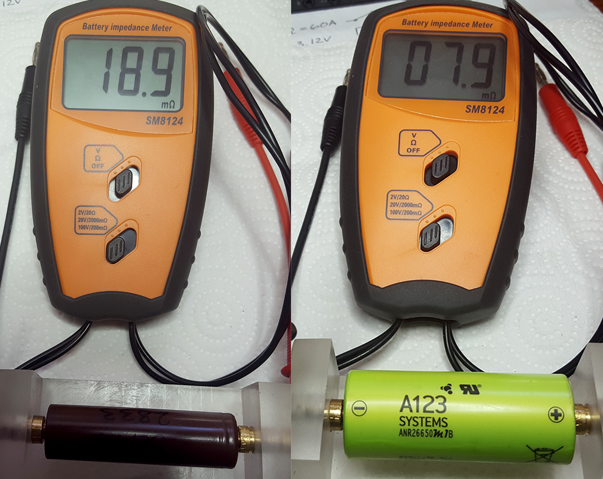
    This is an extraordinary cell that I am rating at 30A. The two cells I received from EnerCig and the two from Nkon appear to have come from the same batch.

    The datasheet has a "maximum continuous discharge" rating of 70A in the datasheet. But at that temperature, about 85°C, the cell will have a significantly reduced cycle life. This rating is an absolute maximum, not a level you should operate the battery at for every cycle. To allow direct comparison against other batteries I am rating this cell at a level, 30A continuous, which limits the temperature to 60°C to ensure good cycle life. Above this temperature the cell's aging accelerates significantly. The cell can easily be pulsed at levels above 80A though.

    This cell's lithium-ferrous-phosphate (LFP) chemistry is the safest of the Li-Ion chemistries we use. While this should never be used as an excuse to do so, these A123's can take a lot of abuse before going into thermal runaway. If they do go into runaway their reaction isn't as violent as the other chemistries.

    The voltage of this cell is very steady for most of the discharge, very similar to LiPo's. This is great for unregulated/mechanical mod users. The iJoy 4200mAh 26650 is a better choice for vaping at up to about 40A though.

    The 26650 ratings table has been updated to include this cell.


    Things To Be Aware Of
    - Their nominal voltage is 3.3V. This means they can't be used in regulated mods and their much lower voltage, when drawing a lot of current from them, probably limits their use to series unregulated/mechanical mods only.

    - These batteries require a 3.6V charger! You cannot charge them to 4.2V.

    - At high current levels the nominal voltage drops to as low as 2.5V.

    - Unregulated or PWM mods using a MOSFET for button protection may not be able to use just one of these cells or use them just in parallel. The nominal voltage will be too low to turn many MOSFETs on fully at higher current levels. This can cause them to overheat and burn out.

    -The "button" end of the cell is the NEGATIVE terminal, not the positive.

    - The metal case of this cell is the POSITIVE terminal, not the negative like the other cylindrical cells we use.

    - Due to the need to operate these in series, and their "reversed" polarity construction, I strongly recommend that only experienced vapers with in-depth knowledge of Ohm's Law, battery safety, and understanding of the ratings and requirements of this cell try using it. If you have questions that you cannot otherwise find the answers to, I urge you to not use this cell.


    Continuous-Current Test Results
    image.png


    Pulse-Current Test Results
    image.png image.png


    ANR26650M1-B Datasheet
    image.png image.png


    Comments
    • At 10A continuous it reached 2452mAh. This is great performance for a low internal resistance cell 2400mAh cell at 10A, and typical for its 2500mAh nominal rating, so I am rating it at 2400mAh.
    • At 15A and 20A continuous the temperature rose to 46°C and 50°C, respectively. This is below the average temperature of a cell operating at its continuous discharge rating (CDR) and is an indication that we are operating below its true rating.
    • At 30A continuous the temperature rose to 59°C. This is a just below the 60°C temperature at which its aging speeds up a lot and is an indication that we are operating at a level that helps to ensure a long cycle life.
    • At 40A, 50A, and 60A continuous the temperature rose to 67°C, 75°C, and 80°C, respectively. The nominal voltage has dropped to about 2.55V at 60A.
    • At 70A continuous the cell is running at below 2.5V, at near 85°C, but its discharge curve is still pretty flat.
    • I am setting a CDR of 30A for this cell. While operating any cell near its rated maximum current level causes damage to the cell, I would expect good cycle life from this cell at 30A continuous.
    To see how other cells have tested and how hard you can safely push them, check out these links:
    List of Battery Tests | E-Cigarette Forum
    https://www.e-cigarette-forum.com/f...afety-grades-and-pulse-performance-data.7566/
    https://www.e-cigarette-forum.com/f...des-picking-a-safe-battery-to-vape-with.7447/
    https://www.e-cigarette-forum.com/f...fety-grades-and-pulse-performance-data.7554//
     
    Last edited by a moderator:

    Barkuti

    Super Member
    ECF Veteran
    May 3, 2016
    319
    410
    48
    Alhama de Murcia, Spain
    Hello! :)
    I find this somewhat odd, in the likes of that discharge HKJ made for the APR18650M1-A.
    The battery is supposed to be charged up to 3,6V, and start dropping voltage steadily down from there but, there's something else. I mean, if you look at the discharge curves, you can clearly notice there's some sort of unusually steep initial voltage drop even for the lowest amp rating curve. The more or less even voltage drop spacing for each adjacent +10A incremental curves makes sense yet, in general, all of the curves seem to sit somewhat lower than I'd have expected. o_O
    Mooch, did you ever thought about making no-load voltage measurements on the cells at steady intervals? I mean, very brief pauses while discharging for voltage measurement. I think this can give very decent feedback about cells' internal resistances and how do they progress on the discharge curves. Well, not that it's that difficult to do by observing the slope evolution of adjacent curves, yet actual numbers can make calculations waaay easier than reading a limited resolution graph to the naked eye. :rolleyes:
    Well, just trying to figure out the reason for such an steep initial voltage drop.
    Thanks for the review, I linked it to BLF the other day: A123 ANR26650M1-B reviewed by Mooch :-) | BudgetLightForum.com

    Cheers :angel:
     

    Mooch

    Electron Wrangler
    ECF Veteran
    Verified Member
  • May 13, 2015
    3,946
    15,441
    Hello! :)
    I find this somewhat odd, in the likes of that discharge HKJ made for the APR18650M1-A.
    The battery is supposed to be charged up to 3,6V, and start dropping voltage steadily down from there but, there's something else. I mean, if you look at the discharge curves, you can clearly notice there's some sort of unusually steep initial voltage drop even for the lowest amp rating curve. The more or less even voltage drop spacing for each adjacent +10A incremental curves makes sense yet, in general, all of the curves seem to sit somewhat lower than I'd have expected. o_O
    Mooch, did you ever thought about making no-load voltage measurements on the cells at steady intervals? I mean, very brief pauses while discharging for voltage measurement. I think this can give very decent feedback about cells' internal resistances and how do they progress on the discharge curves. Well, not that it's that difficult to do by observing the slope evolution of adjacent curves, yet actual numbers can make calculations waaay easier than reading a limited resolution graph to the naked eye. :rolleyes:
    Well, just trying to figure out the reason for such an steep initial voltage drop.
    Thanks for the review, I linked it to BLF the other day: A123 ANR26650M1-B reviewed by Mooch :-) | BudgetLightForum.com

    Cheers :angel:

    Check out my pulsed discharge graphs. They give you a very good look at the effect of internal resistance on the voltage-under-load of the cell. This is what causes the almost instantaneous voltage sag at the start of every continuous discharge or pulse.

    No battery will start discharging at its resting voltage unless the discharge current level is very, very low. The internal resistance will always cause the voltage to sag down within a few milliseconds to a level equal to the resting voltage minus the voltage sag caused by the internal resistance and discharge current level.

    Thanks for the link to the test results. :)
     

    Barkuti

    Super Member
    ECF Veteran
    May 3, 2016
    319
    410
    48
    Alhama de Murcia, Spain
    Thanks for the tip on taking a peek over the pulsed discharge graphs. :thumb:
    I'm going to settle on calling this phenomena “voltage sag inertia”.
    It seems that after an initial steeper voltage drop (which seems greater for LiFePO4s vs Li-ions), the steepness on the discharge voltage curves reduces (less steepness on LiFePO4s vs Li-ions).
    roto2cafe.gif

    The 20C (50A) discharge curve on the official datasheet is quite close to the one you attained. It would be safe to say this is a 50A continuous cell too. :rolleyes:
    A tad expensive maybe, but with a good array of these cells a good starter motorbike/car battery could be made. Mmm, maybe a mixture of lead-acid plus some 4SxP ANR26650M1-A/B LiFePO4 array could more or less fix the fragility of lead-acid starter batteries against deep cycling and their weakness under cold environments… :pop:
    Tad off-topic, yeah. :offtopic:

    Cheers :)
     

    Mooch

    Electron Wrangler
    ECF Veteran
    Verified Member
  • May 13, 2015
    3,946
    15,441
    Thanks for the tip on taking a peek over the pulsed discharge graphs. :thumb:
    I'm going to settle on calling this phenomena “voltage sag inertia”.
    It seems that after an initial steeper voltage drop (which seems greater for LiFePO4s vs Li-ions), the steepness on the discharge voltage curves reduces (less steepness on LiFePO4s vs Li-ions).
    roto2cafe.gif

    The 20C (50A) discharge curve on the official datasheet is quite close to the one you attained. It would be safe to say this is a 50A continuous cell too. :rolleyes:
    A tad expensive maybe, but with a good array of these cells a good starter motorbike/car battery could be made. Mmm, maybe a mixture of lead-acid plus some 4SxP ANR26650M1-A/B LiFePO4 array could more or less fix the fragility of lead-acid starter batteries against deep cycling and their weakness under cold environments… :pop:
    Tad off-topic, yeah. :offtopic:

    Cheers :)

    No, no, no...please don't create any new terms. :)
    The pulse discharges show two things going on...

    1) The almost immediate voltage sag caused by the internal resistance of the battery.
    2) The continuing, but slower, drop in battery voltage due to the battery being discharged.

    You can see this same thing going on in the continuous discharge graph too.

    LCO (lipo) and some LFP chemistry cells do have flatter voltage discharge curves than other chemistries but they all feature the fast initial drop from internal resistance, slightly slower drop after that, then a slow drop where the bulk of the discharge occurs, and the fast drop at the end when the cell nears fully discharged.
     

    Barkuti

    Super Member
    ECF Veteran
    May 3, 2016
    319
    410
    48
    Alhama de Murcia, Spain
    Mooch, let me explain:
    I can observe a delta of ≈0,55V between the 10A and the 60A curves on the continuous discharge graph. Therefore, from such data I can infer the battery has about 11mΩ of internal resistance, isn't it? :)
    Good, but, as I was trying to explain before, if the battery starts discharging right at around 3,6V, shouldn't we be measuring the first 10A load voltage(s) at the battery terminals just below 3,49V in the graph?
    elboinas.gif

    Hope this is more clearly understood now. :D

    Cheers :party:
     

    Mooch

    Electron Wrangler
    ECF Veteran
    Verified Member
  • May 13, 2015
    3,946
    15,441
    Mooch, let me explain:
    I can observe a delta of ≈0,55V between the 10A and the 60A curves on the continuous discharge graph. Therefore, from such data I can infer the battery has about 11mΩ of internal resistance, isn't it? :)
    Good, but, as I was trying to explain before, if the battery starts discharging right at around 3,6V, shouldn't we be measuring the first 10A load voltage(s) at the battery terminals just below 3,49V in the graph?
    elboinas.gif

    Hope this is more clearly understood now. :D

    Cheers :party:

    Yes, at that temperature and state of charge the IR is about 11mOhms.

    The IR is higher at the start of the discharge though, when the cell is cooler. I haven't measured them though.

    But if the IR was the same at the start then, yes, a few milliseconds into the charge the voltage would be a about 3.49V at 10A. But the battery is very quickly discharging down its "surface charge" and dropping to its nominal voltage for that discharge current rate. Anything that happens after the first few milliseconds is a voltage decrease from loss of charge. The internal resistance only has an effect for those first few milliseconds, at the most.
     

    AMDTrucking

    Ultra Member
    ECF Veteran
    Dec 7, 2013
    1,950
    3,232
    California
    Mr. Mooch, about internal impedance of the battery:
    I bought a little Chinese tester @ 1000Hz and it seems to do OK.
    DeEgu6n.png

    Before that, I made a simple voltmeter. Solid stainless steel construction with 10 AWG wire inside.
    fkL06Ai.png

    Pretending that my copper mechanical mod has no internal resistance, I would measure my battery voltage under NO load first U1. Then I would attach my 0.5Ω 100W resistor, that I made for that purpose.
    AOntTSA.png

    And take down the voltage under load U2. I would then subtract U1 - U2 to determent the difference U3. Then I would calculate my current under load: U2 ÷ R = I.
    Then I would divide my voltage sag U3 ÷ I to get my battery internal impedance.
    Example: U1=4.16V, U2=3.86V, 4.16 - 3.86 = U3 0.3V. Then 3.86V ÷ 0.5Ω = I 7.72A. Then 0.3V ÷ 7.72A = 0.0388Ω = 39mΩ (rounded up). It wasn't the best battery, I might add. :laugh:
    Based on my internal resistance and my coil resistance (for example 0.2Ω), I would imagine that at the first push of a button, the current will jump up to 4.16V ÷ 0.2Ω = 20.8A. Voltage drop, on internal battery impedance, will be:
    20.8А × 0.039Ω = 0.8112V. Therefore my running voltage will stay at: 4.16V - 0.8112V = 3.3488V and current: 3.3488 ÷ 0.2Ω = 16.744A and I will be vaping at 3.3488V × 16.744A = 56 Watts.
    But my Chinese tester shows much different results (usually lower). I also have Opus BT-C3400 and SkyRC D100 that can measure internal battery impedance and their measurements are much higher that the other two. What am I doing wrong? How do you measure internal resistance? I hope I'm not boring you...
     

    Mooch

    Electron Wrangler
    ECF Veteran
    Verified Member
  • May 13, 2015
    3,946
    15,441
    Mr. Mooch, about internal impedance of the battery:
    I bought a little Chinese tester @ 1000Hz and it seems to do OK.
    DeEgu6n.png

    Before that, I made a simple voltmeter. Solid stainless steel construction with 10 AWG wire inside.
    fkL06Ai.png

    Pretending that my copper mechanical mod has no internal resistance, I would measure my battery voltage under NO load first U1. Then I would attach my 0.5Ω 100W resistor, that I made for that purpose.
    AOntTSA.png

    And take down the voltage under load U2. I would then subtract U1 - U2 to determent the difference U3. Then I would calculate my current under load: U2 ÷ R = I.
    Then I would divide my voltage sag U3 ÷ I to get my battery internal impedance.
    Example: U1=4.16V, U2=3.86V, 4.16 - 3.86 = U3 0.3V. Then 3.86V ÷ 0.5Ω = I 7.72A. Then 0.3V ÷ 7.72A = 0.0388Ω = 39mΩ (rounded up). It wasn't the best battery, I might add. :laugh:
    Based on my internal resistance and my coil resistance (for example 0.2Ω), I would imagine that at the first push of a button, the current will jump up to 4.16V ÷ 0.2Ω = 20.8A. Voltage drop, on internal battery impedance, will be:
    20.8А × 0.039Ω = 0.8112V. Therefore my running voltage will stay at: 4.16V - 0.8112V = 3.3488V and current: 3.3488 ÷ 0.2Ω = 16.744A and I will be vaping at 3.3488V × 16.744A = 56 Watts.
    But my Chinese tester shows much different results (usually lower). I also have Opus BT-C3400 and SkyRC D100 that can measure internal battery impedance and their measurements are much higher that the other two. What am I doing wrong? How do you measure internal resistance? I hope I'm not boring you...

    Nice voltmeter and mount!

    Internal resistance (IR) is surprisingly hard to measure. Consistency is critical. The IR is very dependent on the temperature and state-of-charge of the battery. Always measure the IR after letting the battery sit for about an hour. I usually charge the battery, let sit for one hour, and then measure. I take three readings and average them.

    One big cause of the difference in IR between your meter and your hand measurements is that the meter measures the AC IR and your hand method measures the DC IR. The DC IR of a battery is always higher but it is the one we're interested in since we run our batteries continuously. Any discharge over a few milliseconds long is considered to be continuous by the battery.

    Another potential problem is the update rate of your voltmeter. It might be too slow to give you an accurate reading.

    For greater accuracy, the current should be as high as possible. But the higher the current the faster the battery discharges, adding an additional voltage drop you don't want in your equation. You just want the voltage reading a few milliseconds after the discharge starts. The longer you wait after that the more the voltage drops from the actual discharge and not the IR of the battery.

    I use the Wayne Giles ESR meter which uses a 15 millisecond pulse. But if you measure as quickly as possible using tour resistor method you might be able to increase your accuracy.

    The Opus and SkyRC are incredible units but, in my experience, aren't very accurate when it comes to measuring IR. There's no real standard for how to measure IR so just about every method produces a different number. This is where a consistent test method is key. Your method might give different results than other methods but, if you test consistently, the relative differences between the cells you test will be very accurate. Also to consider is the resistance of everything between the ends of the battery and the circuit that measures the voltage. All of that resistance gets added to the IR of the battery with those units.

    A great way to check out a method is to take several measurements, one after another, moving the test leads and anything else that is involved. Also take several measurements, back to back and hours or days apart, without moving anything to get a baseline idea of how the battery responds to this. If the measurements taken when moving stuff around or when taken hours apart varies a lot then you have some uncontrolled variables that need to be addressed before you can get accurate and repeatable readings.
     

    showman

    Senior Member
    Verified Member
    Dec 1, 2012
    74
    38
    Brooklyn
    Thanks- just so I understand, if you can adjust the discharge voltage on your regulated mod, this still wouldn't allow you to use such batteries? On my dicodes mods, I think the battery discharge voltage can be adjusted between 2.5v-3.0v (depending on which Dicodes chip is being used, it might go up to 3.5). Perhaps I'm not understanding accurately how this feature works, but my initital thought was that such a feature would allow you to use batteries with variant voltages. But I think that such a feature would have to allow you to set the minimum discharge all the way down to 2.0 for this to work, to not get the low battery message very quickly, if I am grasping this properly.

    In either case, after reading your review more carefully, I guess it still looks like the iJoy would be a better choice, since these only fire up to 20 amps, and you say the iJoy is superior in that range in any case, even on a mech mod (which I don't use.) Just liked what I read about the chemistry and technology here; I wonder if it is technically possible to produce batteries of this kind in the normal voltage range for vaping?
     

    showman

    Senior Member
    Verified Member
    Dec 1, 2012
    74
    38
    Brooklyn
    Let me also point out for anyone interested that these batteries are available from official U.S. distributor here: Authorized Online A123 Battery Cell Reseller...
    For 10-99 26650 batteries, they sell for $9.30 each with a flat $20 shipping. If you need an absolute ton, you can get 100 for $8.75 each, with the same flat $20 shipping.

    They also have the 18650 version of the batteries.

    I think they do come out slightly cheaper from nkon, which charges 8.50 euros (roughly 8.88 USD) and generally 30 Euros delivery; though for about 10 or so, the a123 should come out cheaper because of the lesser shipping, though this may depend on your location.
     
    • Like
    Reactions: Mooch

    Mooch

    Electron Wrangler
    ECF Veteran
    Verified Member
  • May 13, 2015
    3,946
    15,441
    Thanks- just so I understand, if you can adjust the discharge voltage on your regulated mod, this still wouldn't allow you to use such batteries? On my dicodes mods, I think the battery discharge voltage can be adjusted between 2.5v-3.0v (depending on which Dicodes chip is being used, it might go up to 3.5). Perhaps I'm not understanding accurately how this feature works, but my initital thought was that such a feature would allow you to use batteries with variant voltages. But I think that such a feature would have to allow you to set the minimum discharge all the way down to 2.0 for this to work, to not get the low battery message very quickly, if I am grasping this properly.

    In either case, after reading your review more carefully, I guess it still looks like the iJoy would be a better choice, since these only fire up to 20 amps, and you say the iJoy is superior in that range in any case, even on a mech mod (which I don't use.) Just liked what I read about the chemistry and technology here; I wonder if it is technically possible to produce batteries of this kind in the normal voltage range for vaping?

    The LFP chemistry is pretty well stuck at this voltage. Other li-ion chemistries, like the ones we use for vaping, are at the higher voltages we are accustomed to.

    A mod with an adjustable cutoff voltage that goes low enough might be able to be used. There are physical differences involved too. Be sure to check dimensions, contact shape and size, etc.
     

    showman

    Senior Member
    Verified Member
    Dec 1, 2012
    74
    38
    Brooklyn
    The LFP chemistry is pretty well stuck at this voltage. Other li-ion chemistries, like the ones we use for vaping, are at the higher voltages we are accustomed to.

    A mod with an adjustable cutoff voltage that goes low enough might be able to be used. There are physical differences involved too. Be sure to check dimensions, contact shape and size, etc.

    Thanks for this info on the LFP chemistry, and the clarification about adjustable cutoff voltages.
    I might try this, after I have some time to research some of the other issues you highlight. Unfortunately, it does look like the adjustable cutoff voltage on the Dicodes chips I have can only be set as low as 2.5, at present. Plus The chip will also start gradually reducing the wattage gradually once voltage dips below the cutoff point plus 0.5, dropping to 10 watts once the cutoff point is reached. So if I tried using these, I'd be able to get full 60 watts of power with a full 3.6 volt charge, but power would quickly drop to 50 watts once I drop under 3.0 volts and hit 2.9, drop to 40 watts at 2.8 volts, 30 watts at 2.7 volts, 20 watts at 2.6 volts, and 10 watts at 2.5 volts. So even though the battery has 1.6 volts to drop from full peak voltage until cutoff at 2.0, I'd only be able to actually drop 0.6-0.7 of those volts before my wattage also started to drop, which is about 45 percent of the full voltage range of the battery, and would only be able to drop about 70 percent of the actual volts before wattage dropped below 20 watts. Conversely, if I used one of the iJoy batteries, then even if one set the minimum discharge 0.1-0.2 higher with the iJoy (back to the factory settings) to avoid fully discharging it, the iJoy would have a significant advantage in how much voltage can fall before getting wattage dropoff or becoming unusable--starting from 4.2 volts, the iJoy could drop slightly less than 60 percent of the volts before wattage dropoff, and could drop slightly less than 90 percent of voltage before wattage drops below 20.

    Plus, the MaH is almost 60 percent higher on the iJoy; while I don't quite yet understand what the MaH figure means, I gather that it means usage should be 60 percent longer at most settings. So even with adjustable batter cutoff on a mod, the a123 is still probably currently bested by the iJoy, barring very high amp usage over the iJoy's 40 Amp MDR; but if a future chip allowed one to adjust the battery minimum cutoff all the way down to 2.0, then the advantages might start to outweigh the disadvantages for the a123. Having said all this, I'm slightly suspecting I may have completely misunderstood how voltage discharge works, because I don't understand what you mean with this sentence: "The voltage of this cell is very steady for most of the discharge, very similar to LiPo's." In my untutored understanding, I had thought that voltage drops proportionately with the discharge of the MaH for all batteries, but now it seems that it depends on the battery type? If voltage holds steady until the MaH are mostly discharged for the a123, this might make it more attractive (at least for my usage) because I then would not have to worry about wattage dropping steadily as voltage drops (the bane of my existence), which generally leads me to recharge my batteries as soon as voltage drops low enough to start dropping wattage.

    Sorry if any of this was totally off-base or far too long-winded; I'm just learning about batteries recently and have been trying to figure them out and see if I've understood their arcane, esoteric workings.
     

    showman

    Senior Member
    Verified Member
    Dec 1, 2012
    74
    38
    Brooklyn
    Minor technical note to add, on your review.

    You write: "The datasheet has a "maximum continuous discharge" rating of 70A in the datasheet. But at that temperature, about 85°C, the cell will have a significantly reduced cycle life. This rating is an absolute maximum, not a level you should operate the battery at for every cycle. To allow direct comparison against other batteries I am rating this cell at a level, 30A continuous, which limits the temperature to 60°C to ensure good cycle life. Above this temperature the cell's aging accelerates significantly. The cell can easily be pulsed at levels above 80A though."

    I checked the datasheet you post above, and it indeed claims 70A as the Maximum continuous discharge rate, just as you say. However, I just wanted to note that, interestingly, the datasheet presently posted on the a123 website (this might be from their official reseller's website, actually) now lists an Maximum Continuous Discharge Rate of 50A, not 70A: http://a123batteries.com/v/vspfiles/images/pdf/26650.pdf

    Perhaps battery salesman are reading Mooch's reviews and deflating their overrated CDR claims! Still lists a max pulse discharge rate for 10 seconds of 120 A, though.
     

    Mooch

    Electron Wrangler
    ECF Veteran
    Verified Member
  • May 13, 2015
    3,946
    15,441
    Minor technical note to add, on your review.

    You write: "The datasheet has a "maximum continuous discharge" rating of 70A in the datasheet. But at that temperature, about 85°C, the cell will have a significantly reduced cycle life. This rating is an absolute maximum, not a level you should operate the battery at for every cycle. To allow direct comparison against other batteries I am rating this cell at a level, 30A continuous, which limits the temperature to 60°C to ensure good cycle life. Above this temperature the cell's aging accelerates significantly. The cell can easily be pulsed at levels above 80A though."

    I checked the datasheet you post above, and it indeed claims 70A as the Maximum continuous discharge rate, just as you say. However, I just wanted to note that, interestingly, the datasheet presently posted on the a123 website (this might be from their official reseller's website, actually) now lists an Maximum Continuous Discharge Rate of 50A, not 70A: http://a123batteries.com/v/vspfiles/images/pdf/26650.pdf

    Perhaps battery salesman are reading Mooch's reviews and deflating their overrated CDR claims! Still lists a max pulse discharge rate for 10 seconds of 120 A, though.

    Interesting! Thanks :)
     
    • Like
    Reactions: showman

    Mooch

    Electron Wrangler
    ECF Veteran
    Verified Member
  • May 13, 2015
    3,946
    15,441
    Thanks for this info on the LFP chemistry, and the clarification about adjustable cutoff voltages.
    I might try this, after I have some time to research some of the other issues you highlight. Unfortunately, it does look like the adjustable cutoff voltage on the Dicodes chips I have can only be set as low as 2.5, at present. Plus The chip will also start gradually reducing the wattage gradually once voltage dips below the cutoff point plus 0.5, dropping to 10 watts once the cutoff point is reached. So if I tried using these, I'd be able to get full 60 watts of power with a full 3.6 volt charge, but power would quickly drop to 50 watts once I drop under 3.0 volts and hit 2.9, drop to 40 watts at 2.8 volts, 30 watts at 2.7 volts, 20 watts at 2.6 volts, and 10 watts at 2.5 volts. So even though the battery has 1.6 volts to drop from full peak voltage until cutoff at 2.0, I'd only be able to actually drop 0.6-0.7 of those volts before my wattage also started to drop, which is about 45 percent of the full voltage range of the battery, and would only be able to drop about 70 percent of the actual volts before wattage dropped below 20 watts. Conversely, if I used one of the iJoy batteries, then even if one set the minimum discharge 0.1-0.2 higher with the iJoy (back to the factory settings) to avoid fully discharging it, the iJoy would have a significant advantage in how much voltage can fall before getting wattage dropoff or becoming unusable--starting from 4.2 volts, the iJoy could drop slightly less than 60 percent of the volts before wattage dropoff, and could drop slightly less than 90 percent of voltage before wattage drops below 20.

    Plus, the MaH is almost 60 percent higher on the iJoy; while I don't quite yet understand what the MaH figure means, I gather that it means usage should be 60 percent longer at most settings. So even with adjustable batter cutoff on a mod, the a123 is still probably currently bested by the iJoy, barring very high amp usage over the iJoy's 40 Amp MDR; but if a future chip allowed one to adjust the battery minimum cutoff all the way down to 2.0, then the advantages might start to outweigh the disadvantages for the a123. Having said all this, I'm slightly suspecting I may have completely misunderstood how voltage discharge works, because I don't understand what you mean with this sentence: "The voltage of this cell is very steady for most of the discharge, very similar to LiPo's." In my untutored understanding, I had thought that voltage drops proportionately with the discharge of the MaH for all batteries, but now it seems that it depends on the battery type? If voltage holds steady until the MaH are mostly discharged for the a123, this might make it more attractive (at least for my usage) because I then would not have to worry about wattage dropping steadily as voltage drops (the bane of my existence), which generally leads me to recharge my batteries as soon as voltage drops low enough to start dropping wattage.

    Sorry if any of this was totally off-base or far too long-winded; I'm just learning about batteries recently and have been trying to figure them out and see if I've understood their arcane, esoteric workings.

    Compare the shape of the continuous discharge curves for the A123 and iJoys and another 26650 (any one). You'll see a difference in the shapes of the curves and their voltage levels.
     
    Status
    Not open for further replies.

    Users who are viewing this thread