ok... I worked up the nerve to test reverse polarity with the dna using just an external fuse without a FET in line. It took me a while thinking about if I really wanted to try this though. I was thinking 40 bucks down the clinker for a dna if it doesn't work out.
Adding an external fuse prevents overcurrent and reverse polarity damage for the OKR and Naos Raptor boards, but those are buck modules using batts in series while the dna is a boost module using either a single batt or batts in parallel. Didn't know if that made a difference, just wasn't sure, so I've been using a fuse/FET combo with the DNA for my mods that have removable batts to protect from overcurrent as well as reverse polarity.
So... here goes...I used the Efest 30A batts for testing - I didn't care if I blow those pos.")
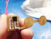
Both batts inserted correctly...

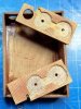
Both batts inserted backwards... both red LEDs are lit indicating both batts are inserted backwards...

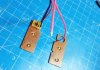
One batt inserted backwards, the other batt inserted correctly...red LED is lit indicating which batt is inserted backwards... the problem with this set up, other than a batt is inserted backwards is that without the red LED indicator there's no system warning and the DNA works fine.

Many many thanks to CraigHB for giving me the incentive to test this.
Note1: for this to work correctly, you need a fuse on each batt if you're running batts in parallel - you can't use a common fuse for both batts else you'll get a batt meltdown from the short when inserting one batt backwards and one correctly.
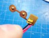
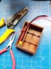
Note2: these are the fuses (wired 2x in parallel) I tested overcurrent and reverse polarity with the DNA20D - 16R300GU and MINISMDC260F/16-2
Adding an external fuse prevents overcurrent and reverse polarity damage for the OKR and Naos Raptor boards, but those are buck modules using batts in series while the dna is a boost module using either a single batt or batts in parallel. Didn't know if that made a difference, just wasn't sure, so I've been using a fuse/FET combo with the DNA for my mods that have removable batts to protect from overcurrent as well as reverse polarity.
So... here goes...I used the Efest 30A batts for testing - I didn't care if I blow those pos.
Both batts inserted correctly...
Both batts inserted backwards... both red LEDs are lit indicating both batts are inserted backwards...
One batt inserted backwards, the other batt inserted correctly...red LED is lit indicating which batt is inserted backwards... the problem with this set up, other than a batt is inserted backwards
is that without the red LED indicator there's no system warning and the DNA works fine.
Many many thanks to CraigHB for giving me the incentive to test this.
Note1: for this to work correctly, you need a fuse on each batt if you're running batts in parallel - you can't use a common fuse for both batts else you'll get a batt meltdown from the short when inserting one batt backwards and one correctly.
Note2: these are the fuses (wired 2x in parallel) I tested overcurrent and reverse polarity with the DNA20D - 16R300GU and MINISMDC260F/16-2