How does the switch and mosfet work in a dual 18650 box mod?

Status
Not open for further replies.

collinsmcrae

Senior Member
ECF Veteran
Sep 20, 2015
101
122
37
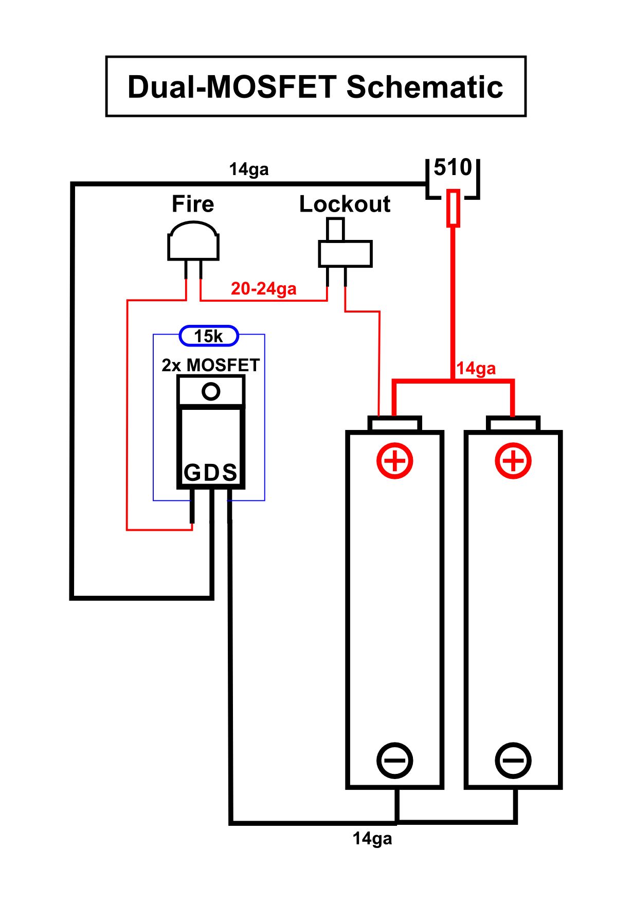
I have been racking my brain trying to understand this schematic. With my limited knowledge on electrical circuits, it looks to me like an atomizer would just auto fire in this configuration. I know that this isn't the case because this is a standard design. But what are the switches inturrupting exactly? How is inturrupting that smal red positive wire preventing the big red wire connected to the 510 from completing the circuit? I'm sorry, but I am a total novice at this point, which is something I intend to remedy. I prefer to understand what I'm doing, rather than just follow instructions. Any information from you non novices out there is always greatly appreciated

0d0e0fb22e5d806df24f1fcd0a4fe6a5.jpg
 

collinsmcrae

Senior Member
ECF Veteran
Sep 20, 2015
101
122
37
the "smal red positive wire" turns on the mosfet,
assuming the schematic is correct for a low side mosfet switch.
Thank you. I think I get it now. So the Mosfet is a switch itself, and requires a low load to activate. This low load is what the firing switch interrupts, which takes the burden of the full load off of it, and let's the mosfet handle the heavy lifting. Is that about the gist of it, or am I still off?
 
Last edited:
  • Like
Reactions: Dougiestyle

Alexander Mundy

Ribbon Twister
ECF Veteran
Verified Member
Apr 1, 2013
4,408
26,095
Springfield, MO
Thank you. I think I get it now. So the Mosfet is a switch itself, and requires a low load to activate. This low load is what the firing switch interrupts, which takes the burden of the full load off of it, and let's the mosfet handle the heavy lifting. Is that about the gist of it, or am I still off?

That's the quick gist of it. The resistor is there to keep the mosfet from firing when the gate is not connected to the battery +. Bear in mind that diagram is for an N channel Mosfet. A P channel will be different. N channel Mosfets are preferred due to lower on resistance. Section of the mosfet is important and the gold standard for mods is the International Rectifier 3034. Avoid ebay unless you expressly know the seller as they are counterfeited quite often. Digikey or Mouser are 2 good sources. Here is the link for the standard TO220 package at Digikey http://www.digikey.com/product-sear...page=1&pageSize=25&ptm=0&pv16=8250&quantity=0
 

collinsmcrae

Senior Member
ECF Veteran
Sep 20, 2015
101
122
37
That's the quick gist of it. The resistor is there to keep the mosfet from firing when the gate is not connected to the battery +. Bear in mind that diagram is for an N channel Mosfet. A P channel will be different. N channel Mosfets are preferred due to lower on resistance. Section of the mosfet is important and the gold standard for mods is the International Rectifier 3034. Avoid ebay unless you expressly know the seller as they are counterfeited quite often. Digikey or Mouser are 2 good sources. Here is the link for the standard TO220 package at Digikey http://www.digikey.com/product-search/en?ColumnSort=0&FV=fff40015,fff8007d&fid=0&fullsite=true&k=3034+mosfet&mnonly=0&newproducts=0&page=1&pageSize=25&ptm=0&pv16=8250&quantity=0
Thanks for the reply! That information is very helpful. I know the tendency with working with small electronics, circuit boards, and transistors is to learn what works, and just a pinch of the "why" that it works. In order to learn exactly how everything works, you'll start to get into some fairly complex physics and chemistry, but it's still nice to learn as much as you can imo.
So what do you think of Nonames printed circuit board that has 2 mosfets, the resistor, and the master switch built in? Advicevise has a build tutorial on his channel using it. He sells diy box mod kits, and I think he sends you these standard now with his unregulated dual 18650 kits now. He even assembles the circuit board for you (I'm guessing it comes in pieces if ordered anywhere else?), so all you really have to do is sodder your wires on the board. It's a lot more compact this way as well.
 

Alexander Mundy

Ribbon Twister
ECF Veteran
Verified Member
Apr 1, 2013
4,408
26,095
Springfield, MO
If you use a genuine IR fet I posted the link to I see no reason to use 2. 1 is more than capable of anything we can throw at it even with dual parallel or single 18650's*. Of course there is also no harm in using 2. If heatsinked properly 1 is capable of 195A* continuous. Of course we don't usually heat sink them but we also don't continuously use them either. What you do have to remember is not to drain the battery (batteries) too low depending on your build resistance. The lower the gate voltage the higher the resistance of a fet is. With this one if you drop down below 3.2 and especially below 3V it will dissipate a lot more heat. You can see the drop off in efficiency in the top 2 charts on page 3 of the datasheet. This is where you could possibly kill it. With 2 series batteries it shouldn't be a concern as you will kill the batteries before you get into that operating region.

*with sufficient gate to source voltage. With 3V VGS it is somewhere around 90A heatsinked. With 2.7V VGS 20A will most likely kill it and 10A operation without a heatsink for too long at 2.7V VGS would most likely be fatal to it.
 
  • Like
Reactions: K3nn0Q
Status
Not open for further replies.

Users who are viewing this thread