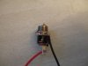
HOW TO: Build the NicoStick

Status
Not open for further replies.

nicowolf

Ultra Member
ECF Veteran
Nov 9, 2008
1,370
15
50
near Akron, OH, USA
Please do not post in this thread. When I have finished posting all the pertinent information, I will put a link to a thread to discuss this mod. I will then ask SunVaporer to sticky this thread so we can easily reference the How To and link to the discussion even years from now.

Pics of the NicoStick:

1851d1240785389-how-build-nicostick-04-26-09-090.jpg
 
Last edited:

nicowolf

Ultra Member
ECF Veteran
Nov 9, 2008
1,370
15
50
near Akron, OH, USA
I bought all my electronics parts from Radio Shack, so part numbers correspond with Radio Shack's catalog numbers.


1 - 2xAAA battery holder Part Number 270-414
1 - 4xAAA battery holder Part Number 270-411
1 - SPST-Mini Momentary Pushbutton Switch Part Number 275-1457
1 - Size N Coaxial Power Jack Part Number 274-1583
 

nicowolf

Ultra Member
ECF Veteran
Nov 9, 2008
1,370
15
50
near Akron, OH, USA
Remove the slide switch from the 4xAAA holder.

To do this:

Remove plastic strip covering wires by gently prying with tweezers. Then use tweezers to push the switch from the exterior of the box so that the spring (soldered to the switch) comes out with it.

Pics:

attachment.php


attachment.php


The 4xAAA battery holder can be thrown out now, all we needed was the switch (and its attached parts).
 

Attachments

  • 4xAAA holder without cover or wire cover.jpg
    4xAAA holder without cover or wire cover.jpg
    21.2 KB · Views: 2,767
  • 4xAAA holder with switch removed.jpg
    4xAAA holder with switch removed.jpg
    22 KB · Views: 2,743
Last edited:

nicowolf

Ultra Member
ECF Veteran
Nov 9, 2008
1,370
15
50
near Akron, OH, USA
Install slide switch in 2xAAA battery holder.

To do this:

Remove the plastic strip covering the wires by gently prying with tweezers.

Remove spring with black wire attached by gently pushing up on it from underneath with tweezers.

Make a hole for switch to protrude through exterior of battery holder. I used my rotary tool to drill a hole, then ream the hole to the proper size. I did not measure ANYTHING. I guesstimated the center of the space and worked from there.

Remove positive contact with red wire attached using the same technique used for the spring with wire attached. SAVE this piece, it will be used later.

Press switch into place making sure to slide the spring into the groove previously occupied by the original spring and wire. I superglued mine in the corners to hold the switch in place so it can't get pushed out accidentally. I also fed my black wire back through the hole to keep it out of the way.

Pics:

attachment.php


attachment.php


attachment.php


attachment.php
 

Attachments

  • 2xAAA holder without cover or wire cover.jpg
    2xAAA holder without cover or wire cover.jpg
    21.3 KB · Views: 2,755
  • 04-26-09 015.jpg
    04-26-09 015.jpg
    16.2 KB · Views: 2,759
  • 04-26-09 017.jpg
    04-26-09 017.jpg
    20.1 KB · Views: 2,746
  • 04-26-09 020.jpg
    04-26-09 020.jpg
    20 KB · Views: 2,759
Last edited:

nicowolf

Ultra Member
ECF Veteran
Nov 9, 2008
1,370
15
50
near Akron, OH, USA
Remove double contact and make hole for atomizer.

To do this:

Use tweezers to gently remove the double contact using the same technique used earlier.

Make a hole for the atomizer. I used my rotary tool and drill bit again to drill a hole and ream it to the right size. The hole should be large enough that the atomizer can twist freely inside the hole.

Place single contact with red wire into the groove next to our new hole. I used tweezers as it is a snug fit. Use tweezers to push wire into the groove where the bridge was for the double contacts (so the wire runs nicely along the side of the battery slot where we are going to put all of our components.

Pics:

attachment.php


attachment.php
 

Attachments

  • 04-26-09 021.jpg
    04-26-09 021.jpg
    21 KB · Views: 2,740
  • 04-26-09 024.jpg
    04-26-09 024.jpg
    20.7 KB · Views: 2,726

nicowolf

Ultra Member
ECF Veteran
Nov 9, 2008
1,370
15
50
near Akron, OH, USA
Make hole for pushbutton switch and cut and bare wires.

To do this:

Same technique as previous two holes. The hole should allow the switch its full range of motion. Do not mount the switch in the box yet. At this point, I had black plastic dust EVERYWHERE and I didn't want that immortalized in epoxy, so I wiped it all down with a damp cloth.

Cut wires slightly longer than they need to be to reach their intended contacts, then bare the ends. The black wire goes to the negative contact for your atomizer connection - in this case, the threads on the DC Jack. The red wire goes to one leg of the switch, it doesn't matter which one.

Pics:

attachment.php


attachment.php


attachment.php
 

Attachments

  • 04-26-09 025.jpg
    04-26-09 025.jpg
    21.4 KB · Views: 2,696
  • 04-26-09 027.jpg
    04-26-09 027.jpg
    21.7 KB · Views: 2,672
  • 04-26-09 031.jpg
    04-26-09 031.jpg
    21.6 KB · Views: 2,683

nicowolf

Ultra Member
ECF Veteran
Nov 9, 2008
1,370
15
50
near Akron, OH, USA
Solder

I usually start with the atomizer connection so I don't have to worry about heat transfering to my switch.

The black wire from the slide switch goes to the negative contact on the atomizer connection (for DC Jack, this is threads; for OEM battery part, this is outer ring).

Red wire from switch to positive contact on atomizer connection (for DC Jack this is a solder prong; for OEM battery part, this is the inner part that looks like a stopper with a hole in it.).

Red wire from positive battery contact to remaining leg of the switch.

I used solder to extend the positive battery contact so it protrudes just a tiny bit into the battery slot to meet the positive contact on the lithium battery (the lithium battery does not have as prominent a bump on the positive end as other types of battery have; check out the last picture).


Pics:

attachment.php


attachment.php


attachment.php


attachment.php


attachment.php
 

Attachments

  • 04-26-09 033.jpg
    04-26-09 033.jpg
    19.6 KB · Views: 2,714
  • 04-26-09 055.jpg
    04-26-09 055.jpg
    21.1 KB · Views: 2,686
  • 04-26-09 056.jpg
    04-26-09 056.jpg
    22.9 KB · Views: 2,701
  • 04-26-09 064.jpg
    04-26-09 064.jpg
    20.2 KB · Views: 2,682
  • 04-26-09.jpg
    04-26-09.jpg
    20.6 KB · Views: 2,629

nicowolf

Ultra Member
ECF Veteran
Nov 9, 2008
1,370
15
50
near Akron, OH, USA
Test, then glue

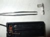
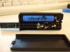
Be sure to test BEFORE you glue. Use your multimeter. (I don't:oops:, but I am telling you the RIGHT way)

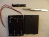
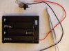
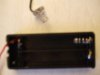
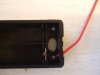
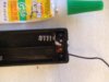
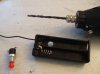
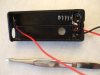
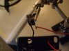
Put all parts into their proper place, with wires arranged the way you want them permanently. Apply epoxy - I used a toothpick for this as the space is quite small and I didn't want epoxy in the wrong places (I accidentally epoxied my atomizer in the first one).

Be patient. Wait at least 20 minutes for the epoxy to set up before trying to vape. Moving the parts before the epoxy is set enough will weaken the joint.

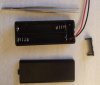
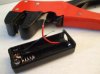
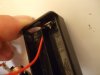
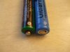
Insert battery and vape out.


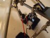
(in case you are wondering why I stress testing with multimeter, I tested mine with a battery and an atomizer before gluing. After the epoxy had set, I put the battery and atomizer back in and tried to vape - my battery got hot real quick and the atty did not - I had a short that didn't show up until everything was glued in place:rolleyes:. Now I have to disassemble my mod and fix it. I hate re-doing what I already did:mad:)

attachment.php
 

Attachments

  • 04-26-09 090.jpg
    04-26-09 090.jpg
    22.1 KB · Views: 5,299
Status
Not open for further replies.

Users who are viewing this thread