LCD Meter Volts/Ohms/Amps/Batt Charge Indicator Wiring for Regulated Mods...

Status
Not open for further replies.

mamu

Ultra Member
ECF Veteran
Verified Member
Mar 29, 2009
2,551
1,523
IN USA
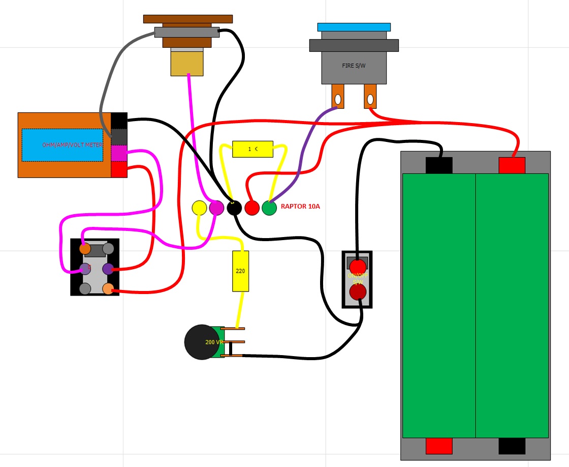
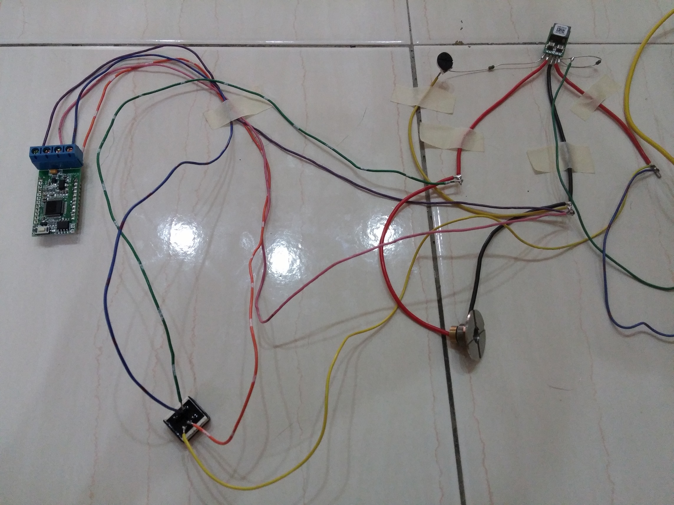
Displays input voltage, output voltage, ohms, amps, and batt charge level.

Just need to get it in a Raptor 20A mod now. woot! :laugh:

lcd-meter-wiring.png
 

mamu

Ultra Member
ECF Veteran
Verified Member
Mar 29, 2009
2,551
1,523
IN USA
All I can say about that friggin programming button, Visus, is don't mess with it. After playing around with it I somehow put it in PAS mode whatever that is, and now I've got a mucked up meter. After hours of trying to reset and trying this and that no-go - everything is off with accuracy - all readings are way high. :(

I've got a request in for help from the seller, so am waiting on a reply.

Curious cat shouldn't be so curious lol
 

Visus

Ultra Member
ECF Veteran
Jun 4, 2013
1,598
851
54
United States
Its in a calibration mode but how to set and lock it in picture instruction is in mandarin..
http://translate.googleusercontent....0.html&usg=ALkJrhi9moVVg90KYs4k1JgESbq-oqBTFA

Just need someone who can interpret it now..

Calibration
Voltage and current measurements need to be calibrated to detect short calibration on power-up jumper, if you enter a short circuit calibration, otherwise normal boot.
After entering the calibration status, follow the prompts LCD standard voltage calibration, the calibration value used is 10V , standard current value of 1A .
Calibration process shown in Figure 3.1 below.
meterlcd.jpg
 

Attachments

  • meterlcd.jpg
    meterlcd.jpg
    8.8 KB · Views: 129

mamu

Ultra Member
ECF Veteran
Verified Member
Mar 29, 2009
2,551
1,523
IN USA
What that's telling you, Visus, is to calibrate the meter you will need to short the calibration button (i.e., press the switch if it's hooked to a switch) and apply 10V source, 1A load.

I have a DC power supply so no biggie with 10V. I don't have a 10 ohm power resistor that will handle 10W though, so will need to get one.

ETA: I heard back from the seller...

Calibration method:
1. to short circuit connect the calibration point .(see the enclosure)
2. At the same time adding 10V input voltage and 1A load current
3. If the final screen display PAS ,and back to normal after 1 second,so calibration success
4. power off, disconnect the calibration points, with electricity can test again.
 
Last edited:

mamu

Ultra Member
ECF Veteran
Verified Member
Mar 29, 2009
2,551
1,523
IN USA
Mory Raptor 20A 120W with LCD meter (displays input volts, batt status indicator, output volts, ohms, amps).

3D printed C frame, sleeve, dual 18650 batt sled, and parts harnesses. The first one shown is woodFill from ColorFabb. The second one (not wired yet) is blue ABS frame, blue ABS dual 18650 batt sled, and black ABS sleeve.

I pre-wired the meter and Raptor before placing in the case, everything else was wired/soldered while in the case... fun NOT lol.

510 connector from Rob Ellard of StealthVape. Mums the word on details for now, but I really like it! Has two especially well thought out features that make it one of the best 510 connectors available to modders. One feature especially all 510 connectors should have but as far as I know none do yet.

mory-1.png


mory-2.png


mory-3.png


mory-4.png


mory-5.png


mory-6.png
 
  • Like
Reactions: JohnnyDill

tchavei

Vaping Master
ECF Veteran
Verified Member
Jul 15, 2014
4,765
8,710
Portugal
I agree on the connector. I had never such low ohm readings as now. Standard 28g ni 200, 10 wraps on a 2.5mm mandrel always read 0.14 on my mods. With the new 510 I got it down to 0.11 ohm and the center pin is massive :)

I like your builds very much. I'm more of a mini sized mod fan but your work looks like art to me :)

Congrats.

Regards
Tony

Sent from my keyboard through my phone or something like that.
 

mamu

Ultra Member
ECF Veteran
Verified Member
Mar 29, 2009
2,551
1,523
IN USA
I've found that there seems to be converter interference with amp and ohm readings if the meter's input/output is connected to any pin of the converter, so take the meter wiring off the pins of the OKR for the +510 and -Batt and wire as I show below and see if that solves the problem.
bfu.png


The DPDT switch needs to handle current. If you're not using a rated switch, you'll need to add an N-FET to take the current load off the switch and wire like this... and remember keep the meter wiring off the converter.
lcd-meter-nfet-wiring2.png
 
Last edited:
Thanks Mamu for your reply,
Actually the above circuit was only for my reference for doing the wiring...
Below is the actual picture of my test bed...
9diX9Ty.jpg

Maybe I should shorten the wire length more...after today I've rewiring as per your suggestion
but the result still the same with just voltage reading available...
Any chance that my meter actually fault rather than the wiring method?
Will update back when I've rewire/reroute properly...
Thanks.....
 
Status
Not open for further replies.

Users who are viewing this thread