Making my first DIY (18650 battery) Sx350 Box Mod - NEED HELP PLEASE

Status
Not open for further replies.

thelukee

Full Member
Nov 14, 2013
24
2
United States
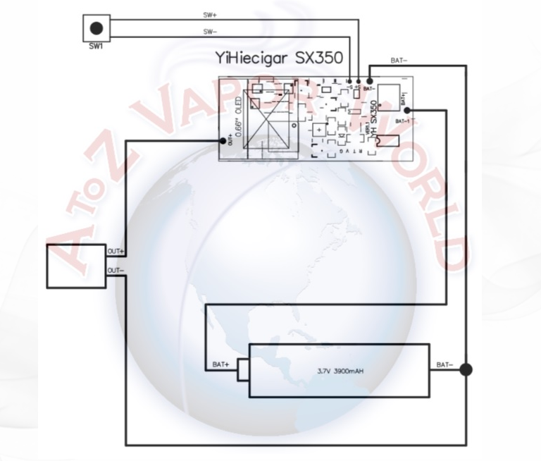
Okay so I know some basic knowledge of circuits and soldering. But please help me out on this, I have no idea what wires go where. Sx350.jpg Can someone please help me out to clarify which wire is which and where it goes? I'm a noob in this area apparently and I can find any tutorials for this anywhere..


I need help with materials I need, I need to make sure I have it all.
Can you guys help me out and put a basic list of everything I'll need to do this... And possibly where to buy it if you were in my shoes. Would pre wired 510 connectors and pre wired battery holders be the way to go?
Alright, thanks.
 

blueGrassTubb

Ultra Member
ECF Veteran
Verified Member
Mar 21, 2014
1,223
824
The Bluegrass
The red and black on the bottom of the chip are the pos/neg from you battery.

The white one on the top is the pos for your atty.

The black ones off to the right are your switch.

You'll also need to run another wire from the negative terminal of your battery to the negative terminal on your 510 atty. If you have the Fat Daddy 510, the negative wire from the battery is soldered on to the underside of the brass nut, and the white wire from the top of the board to the bottom of the positive pin.

You can use 20g or 22g wire. All of the research I've done in the last week or so indicates that those are the standards for box mods. I just received my chip today, and the wires that are soldered to the board are 20g except for the switch wires which are ridiculously small. They also provided 3 extra wires (1 red, 1 black, 1 white) that are all 20g.

I'm about to embark on my SX350 challenge. I know exactly what needs to be wired where, I just need to wait for all of the parts so that I can configure them in the little box I have for it (Hammond 1590A) and learn how to solder better. I bought a couple of "Practical Soldering" kits just for this purpose.

I'll be running dual 3.7v 1S 25C 1200mah LiPos in parallel for a total of 2400mah and a ridiculously high amp rating (60A). I'm using a 20g parallel harness to do this.

Here is a ridiculously simplified wiring diagram for the SX350.

sx350wiring.png
 
Last edited:

thelukee

Full Member
Nov 14, 2013
24
2
United States
The red and black on the bottom of the chip are the pos/neg from you battery.

The white one on the top is the pos for your atty.

The black ones off to the right are your switch.

You'll also need to run another wire from the negative terminal of your battery to the negative terminal on your 510 atty. If you have the Fat Daddy 510, the negative wire from the battery is soldered on to the underside of the brass nut, and the white wire from the top of the board to the bottom of the positive pin.

You can use 20g or 22g wire. All of the research I've done in the last week or so indicates that those are the standards for box mods. I just received my chip today, and the wires that are soldered to the board are 20g except for the switch wires which are ridiculously small. They also provided 3 extra wires (1 red, 1 black, 1 white) that are all 20g.

I'm about to embark on my SX350 challenge. I know exactly what needs to be wired where, I just need to wait for all of the parts so that I can configure them in the little box I have for it (Hammond 1590A) and learn how to solder better. I bought a couple of "Practical Soldering" kits just for this purpose.

I'll be running dual 3.7v 1S 25C 1200mah LiPos in parallel for a total of 2400mah and a ridiculously high amp rating (60A). I'm using a 20g parallel harness to do this.

Here is a ridiculously simplified wiring diagram for the SX350.

sx350wiring.png
Okay that sounds understandable. Im guessing those small wires with the thing attached to it is the micro USB?. Also, as for the box, where do I get a box that can fit the battery, the screen, and the usb port. Also, how the heck do I make sure everything stays in place?
 

blueGrassTubb

Ultra Member
ECF Veteran
Verified Member
Mar 21, 2014
1,223
824
The Bluegrass
Okay that sounds understandable. Im guessing those small wires with the thing attached to it is the micro USB?. Also, as for the box, where do I get a box that can fit the battery, the screen, and the usb port. Also, how the heck do I make sure everything stays in place?

There are various project or hobby boxes you can buy. Hammond boxes are popular. 1590A, 1590B, 1590G are popular models. Radio shack also has project boxes. Do some research. From the research I've done, you can use a high heat epoxy to hold your parts in place.

You'll either have to cut the boxes yourself, or have it done for you. Bapgood has also made some faceplates for the Hammond boxes that will hold everything, but they haven't been tested yet, and I'm pretty sure you'll still need some kind of epoxy to secure the parts inside.

It sounds like you need to research from square one before you even think about starting or buying any parts you might need. Anything you do until you have an intellectual understanding of what needs to be done and a practical understanding of how to do it would almost certainly be a frustrating experience.

You must also remember that I am currently building my first box, so me telling you what to do is based only on research and not any first hand knowledge. It's the 90% blind leading the blind. That said, I have been researching night and day for over a week. I've read everything I can find about how to build around this chip. I know what NEEDS to be done at this point, I just need to practice some soldering and off I go.

Read here on the forums, read elsewhere. Read everything you can about building the SX350. Find pictures of other builds to get an idea of what's going on.
 

thelukee

Full Member
Nov 14, 2013
24
2
United States
Thanks for clarification. Good help. You're the only one lol.
=Last question though... The diagram displays that the negative connection (and the white wire (+) if not mistaken) needs to be soldered to the 510 connection.
I have pre wired battery holders. My logic would be solder the both of the negative connections together then solder that to the 510 connection. So in total there would be three wires attached to it... Correct me if I'm wrong, I'm probably missing something obvious.
Thanks
 

blueGrassTubb

Ultra Member
ECF Veteran
Verified Member
Mar 21, 2014
1,223
824
The Bluegrass
I have pre wired battery holders. My logic would be solder the both of the negative connections together then solder that to the 510 connection. So in total there would be three wires attached to it... Correct me if I'm wrong, I'm probably missing something obvious.
Thanks

That's it, and that's exactly how I'm doing mine.

Make sure that your battery holders have wires that are rated for the amperage. I have a pre-wired battery holder, and even if it did fit in to my box without modification, I'd desolder the wires and solder new ones with a thicker gauge. The one's present are pathetically small if you're going to be pushing any kind of serious amperage.
 

lambjr88

Full Member
Oct 14, 2013
17
1
California
That's it, and that's exactly how I'm doing mine.

Make sure that your battery holders have wires that are rated for the amperage. I have a pre-wired battery holder, and even if it did fit in to my box without modification, I'd desolder the wires and solder new ones with a thicker gauge. The one's present are pathetically small if you're going to be pushing any kind of serious amperage.

Would those small wires presoldered on be a reason why the chip won't push to the max potential? Cuz I wired it to test it and it just wouldn't hit at 35 watts and sometimes it would regulate itself to 10 watts I tried 2 18650s and it gave a hhhhhhhhhh across the screen any ideas on trouble shooting?
 
Which battery holders are you guys using? I am thinking of going with 2 singles next to each other cause all the doubles i am finding are wired wrong and would be a pain in the .... to rewire. The singles have wires on both side which i can easily cut away and resolder new thicker wire to. I really also like the keystone singles as they look pretty legit..

I just dont know.. my chip is coming tomorrow. I got a Hammond 1590B to put her in and a 16mm anti vandal switch all ready to go, ordering VTC5's right now for her too
 

opuscroakus

Super Member
ECF Veteran
Verified Member
Aug 3, 2009
606
114
San Angelo, Tx
Take the flaps and fold them under, that's what I do. I don't think your battery dealer is helping you very well. Running batteries in series carries many more risks than running them in parallel. Also, there are pre-wired parallel 18650 battery holders available. Some have protection built in to them. Still, your best bet is the 1048.

Here is a pre-wired holder with protection. I really don't recommend this but I just wanted to show you that they do exist.

http://www.fasttech.com/products/1425/10002230/1164901-1s2p-3-7v-18650-holder-case-with-build-in-pcm
 
Last edited:

Ohiogators

Moved On
May 3, 2014
33
11
Dayton OH
First of all, check the wires on anything that's prewired. Most of the battery holders that come wired are light gauge with plastic insulation. If they are, cut them off and solder better wire.

The positive wire solders to the pin of the 510 connection. The negative solders to the body of the 510, usually on the nut that threads in the end.

You can solder the 3 negative wires together wherever you like.

You can cut the Hammond box with a dremel and a carbide bit, or a micro cutting wheel, or use a drill and drill a series of small holes if you don't have a dremel. With any of these methods, you're gonna need a needle file to finish them by hand. That's the best way to get good tight fits.
 

blueGrassTubb

Ultra Member
ECF Veteran
Verified Member
Mar 21, 2014
1,223
824
The Bluegrass
I have not seen anyone talk about a fuse for safety! On my mod I used an automotive mini fuse 7.5 amps for the DNA20 with one 18650.

Because a fuse with the SX350 is a redundancy (probably with the DNA chips too), not a requirement. The chips should trip the circuit if need be.
 
Status
Not open for further replies.

Users who are viewing this thread