
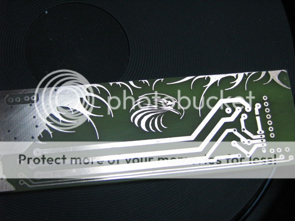
Just got done etching my new board. Now i get to see if i can solder 16 pads in a 4mm x 4mm space. If you never hear from me again it means i more then likely went blind.


Yes etching is very nice and easy too
love it not to have any wires and just make a design that i can put out of the box. easy to clean
Cool looking board Java, and I see the motivation with the 80100w. Even with a 2mm pin pitch DIP socket in between, there's bending and the chip doesn't go in all the way. If you would make a generic 1.7mm pcb board 6x5 hole, I would be quite interested. Heck, I only need 4 rows.
Wow Java, that is fantastic, wish I knew how.
Now that would be awesome in a clear box.
I will design a generic circuit for the chip and release it as open source hardware. Then anyone can make one with a laser printer , hot iron and etching solution. Just need a common parts list to whip it up.
") All availble at Digikey 'cept the Peroxide, the Acid and the tub (not sure abotut the drill press but they have bits). Then add the PCB software (try Express PCB (as long as it's not for commercial production or you use their PCB fab services I think you're OK)
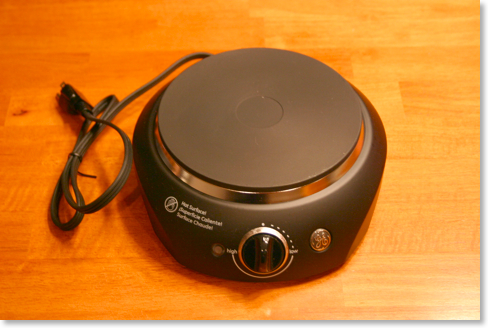
All availble at Digikey 'cept the Peroxide, the Acid and the tub (not sure abotut the drill press but they have bits). Then add the PCB software (try Express PCB (as long as it's not for commercial production or you use their PCB fab services I think you're OK)Or you could try one of these

Wow. A Turntable. Oh The memories.
Thanks IcingdethWow when you get that all set up and tested lemme know and ill buy, awesome work
Just got done etching my new board. Now i get to see if i can solder 16 pads in a 4mm x 4mm space. If you never hear from me again it means i more then likely went blind.