Features:
16A, 88W
Input: 4.5 - 14V
Output: 0.69 - 5.5V
Adjustable UVLO
2 versions - PTH08T220W and PTH08T221W. I chose to work with PTH08T221W (ceramic cap version).
Datasheet here: PTH08T221W
Tiny profile for a 16A module (23mm x 20mm x 9mm)...

Size comparison with the OKR-T10, OKL2-T20, and Raptor 20A...

So I go to solder wire to the pins to get it breadboarded and start by tinning the pins on the board. The instant I touched the pin with the soldering iron - the friggin pin loosened and tilted sideways. All of them, except pin 3, immediately loosened and tilted when I touched the soldering iron to it. gawd lol.
I spent the next half hour or so using flux and a desoldering braid to remove all solder in all the pin holes. It actually turned out to be an advantage that the pins came off because now I have a through hole module for wiring and with even a lower height.
Height between the through hole version compared with as it comes from the manufacturer...

All wired up but holy moly - see how close some of those onboard components are to the pins? This would not be recommended for someone new to soldering...

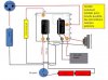
I'm not using Track, Sync, and TurboTrans. As per datasheet, connected Track to Vin, Sync to ground, and TurboTrans open. All other pins of this converter are in use and wired as shown in the above pic.
I connected Track on the front of the board...

and Sync to the back of the board... I lined the back of the board with several layers of Kapton tape first...

Added 3x 100uF (parallel) input and output ceramic caps to the back of the board... I'll either secure these caps with epoxy or change where I placed them before putting the converter in a mod...

Now breadboarded...

I'm using a 1K POT plus 4.7 ohm trim resistor for an output voltage range of 3.5 - 5.6V.
An NC fire switch is required to turn on/off inhibit - the inhibit of this converter requires a switch that must be closed in order to turn OFF output and open in order to turn ON output. That's the short layman's version - read the datasheet for the reason behind this.
I removed the NC switch and took the pic above with an NO tact switch - didn't have to press the button.
I'm not keen on NC switches plus there is a very limited supply and type. If I can't find a work around, what I'll probably do is use a FET to handle current and wire in a non-rated NO switch on Vin. The datasheet indicates that I should still have UVLO with this configuration with the appropriate resistor placed between inhibit and ground.
I've emailed TI tech support with some questions and am waiting to hear back.
Next step is to test the UVLO feature. I bought resistors to test at different voltage cutoffs - 6.0V, 6.2V, 6.4V and 6.5V.
16A, 88W
Input: 4.5 - 14V
Output: 0.69 - 5.5V
Adjustable UVLO
2 versions - PTH08T220W and PTH08T221W. I chose to work with PTH08T221W (ceramic cap version).
Datasheet here: PTH08T221W
Tiny profile for a 16A module (23mm x 20mm x 9mm)...
Size comparison with the OKR-T10, OKL2-T20, and Raptor 20A...
So I go to solder wire to the pins to get it breadboarded and start by tinning the pins on the board. The instant I touched the pin with the soldering iron - the friggin pin loosened and tilted sideways. All of them, except pin 3, immediately loosened and tilted when I touched the soldering iron to it. gawd lol.
I spent the next half hour or so using flux and a desoldering braid to remove all solder in all the pin holes. It actually turned out to be an advantage that the pins came off because now I have a through hole module for wiring and with even a lower height.
Height between the through hole version compared with as it comes from the manufacturer...
All wired up but holy moly - see how close some of those onboard components are to the pins? This would not be recommended for someone new to soldering...
I'm not using Track, Sync, and TurboTrans. As per datasheet, connected Track to Vin, Sync to ground, and TurboTrans open. All other pins of this converter are in use and wired as shown in the above pic.
I connected Track on the front of the board...
and Sync to the back of the board... I lined the back of the board with several layers of Kapton tape first...
Added 3x 100uF (parallel) input and output ceramic caps to the back of the board... I'll either secure these caps with epoxy or change where I placed them before putting the converter in a mod...
Now breadboarded...
I'm using a 1K POT plus 4.7 ohm trim resistor for an output voltage range of 3.5 - 5.6V.
An NC fire switch is required to turn on/off inhibit - the inhibit of this converter requires a switch that must be closed in order to turn OFF output and open in order to turn ON output. That's the short layman's version - read the datasheet for the reason behind this.
I removed the NC switch and took the pic above with an NO tact switch - didn't have to press the button.
I'm not keen on NC switches plus there is a very limited supply and type. If I can't find a work around, what I'll probably do is use a FET to handle current and wire in a non-rated NO switch on Vin. The datasheet indicates that I should still have UVLO with this configuration with the appropriate resistor placed between inhibit and ground.
I've emailed TI tech support with some questions and am waiting to hear back.
Next step is to test the UVLO feature. I bought resistors to test at different voltage cutoffs - 6.0V, 6.2V, 6.4V and 6.5V.
Last edited: