Reverse Polarity Protection with the DNA20D

Status
Not open for further replies.

mamu

Ultra Member
ECF Veteran
Verified Member
Mar 29, 2009
2,551
1,523
IN USA
I've been tinkering trying to solve this issue with my mods that have user replaceable batts.

Not having much luck so far. :(

First up - I used a schottky diode. Works great for reverse polarity protection, but is not feasible due to the input voltage drop. With the narrow vaping voltage range we have in our mods, losing .3v - .5v on the input leaves very little vaping time between charges. No problem on the output, just the input. Plus I found a major bugaboo under load.

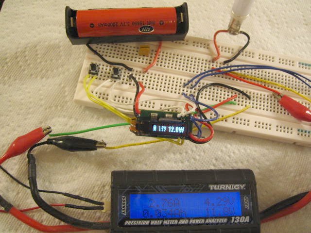
Here's the DNA20D breadboarded without the diode and in line with a watts meter... I have a fully charged batt... notice no loss of the the batt status bars shown on the display while under load...
rp-diode1.jpg


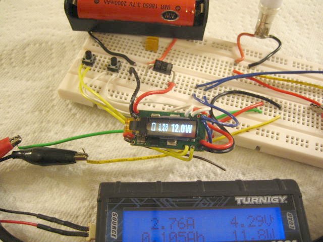
Here's the setup with the diode... fully charged batt... notice the severe drain under load as indicated by the drop in batt status bars on the display... you only get a few presses of the fire button before getting check/weak battery - even with a fully charged batt... the forward voltage rating on the diode I used is 0.42v...
rp-diode2.jpg


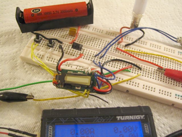
Here's the batt inserted backwards and yes, the diode fully protects against reverse polarity. The DNA20D was up and running once I inserted the batt in correctly.
rp-diode3.jpg


So... no go on the diode due to the loss of input voltage and severe drain under load.

Then I tinkered with a P-FET.

Gate > - input
Drain > + input
Source > + output

Ran into a major problem in that once it was breadboarded and up and running with the P-FET inline, the atty is always firing - with and without pressing the fire button - and when the fire button is pressed, the display shows check atomizer. gawd. :laugh:

Tried changing the Source to one terminal of the fire button - no go, and then the other terminal of the fire button - no go. I don't know how this is configured on the board, but it created a short as everything got hot hot hot. When I noticed this, I pulled the P-FET and it actually burned my fingers a bit. But the DNA20D still works. :laugh:

When I was tinkering with touch switches, I had this same issue - the atty always firing with and without pressing the fire button.

Emailed Brandon asking if there is a work around for this, waiting for a reply. Didn't try putting the batt in backwards yet to test the P-FET for reverse polarity protection as saw no reason to if it's not working as is.

Anyone have any other suggestions?
 
Last edited:

bapgood

Vaping Master
ECF Veteran
Verified Member
Apr 16, 2012
4,426
6,599
43
Utah
Can you tell how the Novel is doing its RP protection?

However it is doing it, it looks to be compact and efficient or you would have noticed by now.

I'm totally perplexed on how a p-fet at the input is firing the devise. Regardless of the other I would like to the how and why of that.

Food for thought.....I believe the added resistance of the breadboard can sometimes cause havoc when testing fet's.
 

mamu

Ultra Member
ECF Veteran
Verified Member
Mar 29, 2009
2,551
1,523
IN USA
Novel? wut dis Novel? :laugh: No, I don't know how the Nivel is doing reverse polarity protection.

I breadboarded the most basic of setups with just the input +, - (batt), fire button, and output +, - (atty). Put the P-FET inline and get the exact same as with the DNA20D - always firing the atty without pressing the fire button.

So it is a FET issue. Maybe the gate threshold voltage vs the 4.2 batt voltage since the FET is always on?

I am self-taught electronics and some parts of the datasheet are Greek to me :laugh:, but here's the P-FET I chose...

SUP75P03-07-E3

I chose it based on 3 things:
1 - Drain-Source max voltage > Vin
2 - Gate-Source max voltage > Vin
3 - Lowest RDS(on)

The gate threshold voltage for this P-FET is min -1v, max -3v. Do you think that's it? If it is, how can I finagle that so the P-FET isn't always on?

Any suggestions would be helpful. I'd really like to get this figured out.
 

mamu

Ultra Member
ECF Veteran
Verified Member
Mar 29, 2009
2,551
1,523
IN USA
From what I understand watching the video, the clamping diode and resister are only there if the Vgs max voltage is close to the input voltage. In his example he used a 12v batt and was talking about a P-FET with a Vgs of 15v - so he was saying a zener + resister was needed for this P-FET with a Vgs of 15v to work.

I breadboarded it anyway with a zener diode acorss gate and source and 100K resister gate to ground and no go - the P-FET is still always firing the atty. :(
 

DrMA

Ultra Member
ECF Veteran
Jan 26, 2013
2,989
9,887
Seattle area
Yeah, I got confused, it was late... Your FET has a Vth(max) of -3V not Vgs.

I don't understand why the DNA 20 is firing if you put the FET on the input. But in your other example with just a batt, atty and FET, it's actually supposed to be always on, unless you reverse polarity on the input, in which case it should turn off.
 

mamu

Ultra Member
ECF Veteran
Verified Member
Mar 29, 2009
2,551
1,523
IN USA
...Does the FET work as you think it should not connected to the DNA?

With just a basic setup, the FET is firing the atty without pressing the fire button, same as with the DNA20D. If it were working like it should, the FET shouldn't be firing the atty.

Can you clarify just to be sure where you have the FET in the circuit?

For the basic setup:
- batt (- input and - output common) > Gate
+ batt > Drain
+ atty connector > Source

For DNA20D:
- batt > Gate > DNA20D - input
+ batt > Drain > DNA20D + input
DNA20D + output > Source > + atty connector
 
Last edited:

DrMA

Ultra Member
ECF Veteran
Jan 26, 2013
2,989
9,887
Seattle area
Source is connected to the + load.

pfet2a.jpg

Well, now I know why the atty is firing. Since the (-) is common to on the input and output, the FET closes the (+) circuit from the battery to the atty directly, sidestepping the DNA altogether.

I'd connect the FET like this:

G: bat - & DNA input - (common)
D: Bat +
S: DNA input +

The "load" in the picture below is the entire DNA module itself (ignore the voltage specs).
p-fet-reverse-voltage-protection1.png
 
Last edited:

mamu

Ultra Member
ECF Veteran
Verified Member
Mar 29, 2009
2,551
1,523
IN USA
...I'd connect the FET like this:

G: bat - & DNA input - (common)
D: Bat +
S: DNA input +

ZOMG!! It works with this configuration.
woot.gif


Thank you thank you thank you for posting the configration DrMA, and thank you dr g and bap for your help and suggestions.

Huge tackle hug to you guys for taking the time to help me!! :wub:

Major happy dance going on now. I have reverse polarity protection with the DNA20D.
:rickroll: :rickroll: :rickroll: :rickroll: :rickroll: :rickroll:
 
Last edited:

mamu

Ultra Member
ECF Veteran
Verified Member
Mar 29, 2009
2,551
1,523
IN USA
I think you can tell I was excited to see the P-FET working. :laugh: This foray into FETs was a new adventure for me and a good learning experience and I very much appreciate you guys taking the time to help.

After doing some testing, I am seeing a major drain under load (especially at the high watts I vape at) similar to what I saw with the schottky diode. If I remove the batt and then re-insert it, the DNA resets, but after a few presses of the fire button, I get the check/weak battery message.

That's with using a single 18650 IMR batt (5C, 10A). That 10A discharge rating may not be suitable in conjunction with a FET, so I'm going to try dual 18650 batts (20A) and the MOLI 26700 (40A) to see if I get better results with the drain under load.
 
Last edited:

DrMA

Ultra Member
ECF Veteran
Jan 26, 2013
2,989
9,887
Seattle area
....
After doing some testing, I am seeing a major drain under load (especially at the high watts I vape at) similar to what I saw with the schottky diode. If I remove the batt and then re-insert it, the DNA resets, but after a few presses of the fire button, I get the check/weak battery message.

That's with using a single 18650 IMR batt (5C, 10A). That 10A discharge rating may not be suitable in conjunction with a FET, so I'm going to try dual 18650 batts (20A) and the MOLI 26700 (40A) to see if I get better results with the drain under load.

If the DNA works well with those batteries without the FET, and it shows the "Check battery" error with the FET, it indicates that the FET isn't turned all the way on and you're not operating in the linear part of the Vgs-Id curve.

If my math is correct, in this application, Vgs is -2.7V (nominal), which is a bit on the low side for this FET. Here's how I calculated it:
Vd=Vbat=3.7V (nominal)
Vs=Vd-V(FET body diode)=3.7-1.0=2.7V
Vg=0V
So, Vgs=0V-2.7V= -2.7V (nominal)

So the FET is partially on, operating with a relatively large Rds(ON), causing significant voltage drop over the DS junction. You should be able to measure this voltage drop with a multimeter.

Bottom line, I think you need a different FET, with a Vgs-Id curve that puts Vgs=2.7V in the linear portion of the curve.
 
Status
Not open for further replies.

Users who are viewing this thread