
I jumped into my project tonight after a nap today. Kind of weary about getting into the soldering as the pins on the converter seem so close to me; but I am not ready for that quite yet anyway. I have drilled out te hole for the pot and atomizer and placed them in the box already. I am still waiting for a few switches so the only thing I am going to try to do yet until they get here is getting the voltage meter hole cut in the box. This is another thing that may be difficult for me because I do not have a dremel and do not want to purchase 1 just for thetwo mods I am going to be doing; this one and one with 2x18650 batteries.
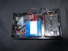
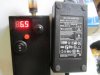
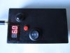
Here are my parts minus two switches that have not arrived yet.

Capecad are you sure the capacitors will not cause a problem. I will take your advice if you tell me to install them, but I think I am still going to use a NC switch to activate the converter control pin unless of course you talk me out of it before Monday by some chance.
Any suggestions would be appreciated; I spent more money on this project than I should have; parts cost me about 85.00 with the batteries and charger.
Thanks everyone
Todd
Here are my parts minus two switches that have not arrived yet.
Capecad are you sure the capacitors will not cause a problem. I will take your advice if you tell me to install them, but I think I am still going to use a NC switch to activate the converter control pin unless of course you talk me out of it before Monday by some chance.
Any suggestions would be appreciated; I spent more money on this project than I should have; parts cost me about 85.00 with the batteries and charger.
Thanks everyone
Todd


 , I would have stepped on it before the first IC was soldered. 8-o