2 Questions

Status
Not open for further replies.

punchy187

Senior Member
ECF Veteran
Feb 19, 2012
116
13
Arizona
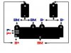
I bought a PCB Battery Holder and I was told it would work with the batteries in series as it even says on the stickers 2S1P 7.4 volt but the stickers inside show in parallel. When I look at the way it is connected to the PCB board I am confused because the terminals are yet again labeled completely different from the previous ones I used. So I am trying to figure out if I can re-wire the PCB battery Holder so I can use it in series but I need to clarify how to do that. So if someone knows what the terminals are please fill me in. The picture is attached.

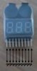
Second question is the voltage reader display and how that is supposed to be connected. There are only two available options...positive or negative but the are nine terminals. What goes to what? Picture is attached. Thanks.
 

Attachments

  • pcbBatteryHolder.jpg
    pcbBatteryHolder.jpg
    11.9 KB · Views: 19
  • Photo0815.jpg
    Photo0815.jpg
    5.9 KB · Views: 17

BJ43

Vaping Master
ECF Veteran
Verified Member
Nov 27, 2008
5,896
7,212
82
Many battery holders you can change the terminals for either series or parallel. For series you wany the batts to be
+(batt)-+(batt)-
On the meter the first pin is ground the rest are positive and for reading up to 8 cells. Normally just use the second pin for positive. Here is how I wire my meters.
Meter-1.png
 

johnpencraig

Full Member
Verified Member
May 29, 2011
58
6
Wales
Punchy, is this the holder you're using?

Capture-2.jpg


If so. it's ok - I had the same confusion with the stickers, but it does output 7.4v (actually 8.4v charged) - there are 2 stiff wires that go separately from the +ve end to the pcb, which then does the series connection thing (somehow!).
I.I.R.C., once it's set up with the batteries in place, it has to be connected to a charger to get it going (technical terminology there)
If you've not got a charger, this one works with the holder - DC 8.4V 1A Charger: 2S 7.4V LiIon LiPo Battery Pack US2 | eBay
 
Last edited:

punchy187

Senior Member
ECF Veteran
Feb 19, 2012
116
13
Arizona
Ok thanks. Seeing your regulator in the diagram reminds me of another question. I have a regulator also and the terminals are (in+) (in-) (+) (out). I am assuming both batteries need to be connected to the regulator like an external PCB board would be so I would connect the one battery positive to (in+) negative to (in-) and the other battery positive to (+) and negative to (out) without a common? Things would be much easier if these parts had standard symbols instead of whatever they want to put on it. I attac hed the picture. Thanks.
 

Attachments

  • Photo0817.jpg
    Photo0817.jpg
    20.5 KB · Views: 11

Topper

Senior Member
ECF Veteran
Verified Member
Nov 3, 2011
115
47
52
Bulgaria
Many battery holders you can change the terminals for either series or parallel. For series you wany the batts to be
+(batt)-+(batt)-
On the meter the first pin is ground the rest are positive and for reading up to 8 cells. Normally just use the second pin for positive. Here is how I wire my meters.
Meter-1.png

Sorry for stealing the topic, but how to make it if I want to measure two voltages - one after regulator and one before (just to monitor batteries levels) ?
When connect two power sources to almost same digital indicator (but 1s-6s w/o buzzer) first measure after regulator is fine between negative and 2nd pin and second value before regulator stright from the battery pack on negative and 3rd pin (2s) is hm so strange ?
Is it there a specific sheme ?
 
Last edited:

BJ43

Vaping Master
ECF Veteran
Verified Member
Nov 27, 2008
5,896
7,212
82
Sure it is, I know series connection of batteries.
My question was for 1s-6s voltage display and strange numbers when there are connected two power sources (from batteries and from convertor)
Anyone else.... who uses two voltage measurement ?
The display is designed to read individual batt volt in series and then gives a sum of the total. When you set it up as you say and it reads the in v and then the out v of the regulator it messes with the program and usually doesn't work, that is why I set it up with a on off on switch to select the source.
 
Status
Not open for further replies.

Users who are viewing this thread