A variable volt "lab power box" - ready to start mod designing

Status
Not open for further replies.

McDude

Senior Member
ECF Veteran
Nov 17, 2010
96
29
Oregon
I started vaping maybe 2-3 months ago and, since then, have really begun to realize that vaping is more of a hobby (a lifestyle per-se) than anything else. I became facinated with the electronics behind it and, like many, rather than resigning myself to spending hundreds on other people's inventions - I decided I'd learn basic electronics and make my own. I'm not the type of person who just builds what someone else designed and not understand it, I have to understand it as well as be able to build it.

To that end, I used a variable volt regulator presented in various posts as an "easy 5v mod" to create instead a lab power box. The box was designed to provide power to test circuits so that I could "dial in" whatever source voltage I wanted - even simulate battery dissipation to test the effect on the various circuits that I want to create. I hope this helps anyone else wanting to "start" modding (and yet understand it too) - step 1: create a power source.

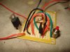
Here is the voltage regulator - soooo simple, hook-up basically any input and dial-in whatever output (within the acceptable ranges of course) that is needed.
DC-DC Converter Board regulator In:3-30V Out:1.3-18V - eBay (item 300459975900 end time Dec-23-10 22:28:48 PST)

All the parts were obtained from ratshack except the switch (a stylish little number I picked up from walmart). I used a 20VDC 4.5A laptop (lenovo) power block as the source, affixed the regulator to that power source (on raised clips) and then simply wired in the rest after cutting up the box as needed.

DSC02010.jpg

DSC02011.jpg

DSC02012.jpg

DSC02013.jpg

Now to add a solderless breakboard and start playing with a number of mod circuits that I've been reading so much about (MOSFET here I come).
 

Sewknitty

Ultra Member
ECF Veteran
Nov 12, 2010
1,425
98
NY
shesaquitter.wordpress.com
Vaping is a hobby and lifestyle and I love to see people admit it! It's been a good distraction as I recover from my analog addiction and I see many more mod purchases in my future!

Variable voltage is seriously on my wish list (along with some kind of feed or tank) but I don't have the tools or inclination to design such myself. Good on you for making the exact mod you want.

Enjoy your hobby and please keep sharing your progress! :D
 

McDude

Senior Member
ECF Veteran
Nov 17, 2010
96
29
Oregon
Thank you! :)

I just finished my first experimental circuit, dialed the lab power to 6.5 volts and nothing smoked, it actually worked like a charm first go (which greatly shocked me hehe, not literally of course, pun intended). Yes, I do want access to the modder's forum haha, but have to do the 5 posts thing, so thought I'd share this stuff here.

Here's an investigation circuit with a MOSFET (IRF510) and 5v regulator (TI). Something isn't quite right - although it works, disconnecting the regulator from ground via the MOSFET yields results I didn't anticipate, - so works but I need to investigate the circuit further. Interesting that vaping piqued my interest in electronics - 60 days or so I didn't know what a resistor did and was still busy sucking analogs. So to anyone who thinks it's "beyond them", well it's not :)

Of course I've been researching endlessly for weeks, but tonight it all came together :)

My first circuit ever. (hope the image posts, different method when replying)

asset.php
 

Attachments

  • DSC02016.jpg
    DSC02016.jpg
    20.2 KB · Views: 29

McDude

Senior Member
ECF Veteran
Nov 17, 2010
96
29
Oregon
By the way, here is what I think is an excellent online tool for anyone interested in learning basic electronics. It's a circuit simulator and extremely easy to use. It has limitations to be sure, but for learning how circuits "flow" and how resistance works, it's great (especially since it's free).
http://www.falstad.com/circuit/
 

CraigHB

Ultra Member
ECF Veteran
Jul 31, 2010
1,249
314
Reno, Nevada
There's a couple ways you can do what you're trying to accomplish. You can either use a P-channel MOSFET to switch power on and off to the regulator or use a regulator with an enable pin. Though, there's always a tiny amount of current draw when the regulator is disabled so it's probably better to use a MOSFET, no leakage. Here's a circuit that works, I'm using this one for my own battery-less passthru, photos below. Just replace the box that says "Atty" with the regulator circuit and use whatever voltage you want instead of 5V. The MOSFET is good for 30V and 13 amps.

And yea, modding is a blast, working on a new one myself right now.

passthru.jpg


hotwire.jpg
hotwire2.jpg
 
Last edited:

CraigHB

Ultra Member
ECF Veteran
Jul 31, 2010
1,249
314
Reno, Nevada
You can use an N-Channel, but the problem is the the small voltage drop you get across the MOSFET offsets the ground potential for whatever you are switching. You can end up with ground loops that way. I mainly use N-channel MOSFETS as signal drop downs and P-channel MOSFETS as power switches. Sometimes, I use an N-channel to provide the gate signal to a P-channel switch. In the circuit I posted, you could replace the manual switch with an N-channel and control the switch with a mircoprocessor or microcontroller.
 

o4_srt

Super Member
ECF Veteran
Jun 2, 2010
816
13
Lancaster, PA
Thanks CraigHB, really good information. I'll give P channel a try too. I resolved my original problem, instead of using the N channel on the regulator ground, I switched it to the attomizer return and the circuit behaves as expected but there is the voltage drop you mentioned. Off to design an N + P setup :) "Thanks again.

the problem with this is implementation is that the regulator is constantly "on," and will wear down your batteries. Your atty is not firing, but there is still current going through your regulator, called leakage current. It is usually a very small amount (uA or less), but still contributes to decreased battery life. I'm trying to figure out a way to use a MOSFET to cut power to the regulator itself via using a MOSFET on it, minimizing leakage current. The MOSFET will be incorporated between the bypass cap and the regulator, further increasing battery life by keeping the bypass cap charged.
 

CraigHB

Ultra Member
ECF Veteran
Jul 31, 2010
1,249
314
Reno, Nevada
Some regulators can have pretty high quiescent current so you definitely need to consider that. Depending on the bypass capacitor, you may or may not want to keep it charged. Some can have considerable leakage, but they can also wear out fast due to repetetive surge. I just ran into that problem myself. I'm doing a mod that uses a DC-DC step-up converter. The converter uses a couple high value, small package capacitors each with about a microamp of leakage. Since I need to minimize standby current, every little bit helps. I couldn't decide whether I should leave them charged or not. I ended up leaving the caps charged all the time because the repetetive surge currents would wear them out too fast. Those surges are also hard on the MOSFET switch and flywheel diode. My circuit boards are supposed to be here today so I'm anxious to see how my design is going to work out. Keeping my fingers crossed.
 

VaporChef

Super Member
ECF Veteran
May 27, 2010
319
103
NYC, USA
McDude! You eloquently expressed exactly what I have been thinking the past few weeks!

I started off right away doing DIY juice, but was intimidated by the prospect of soldering until I remembered that 25 years ago I did decent welding work... how can soldering be hard after that? Plus, the cost of VV mods is enough to make me want to build my own (I'm that kind of girl, happily geeky) and I'm always up for learning new skills. So I have gone half blind reading about electronics, soldering and circuits... then online shopping for the tools and parts I'll need to get.

Your can-do attitude is inspiring, I like your idea!
 

o4_srt

Super Member
ECF Veteran
Jun 2, 2010
816
13
Lancaster, PA
Some regulators can have pretty high quiescent current so you definitely need to consider that. Depending on the bypass capacitor, you may or may not want to keep it charged. Some can have considerable leakage, but they can also wear out fast due to repetetive surge. I just ran into that problem myself. I'm doing a mod that uses a DC-DC step-up converter. The converter uses a couple high value, small package capacitors each with about a microamp of leakage. Since I need to minimize standby current, every little bit helps. I couldn't decide whether I should leave them charged or not. I ended up leaving the caps charged all the time because the repetetive surge currents would wear them out too fast. Those surges are also hard on the MOSFET switch and flywheel diode. My circuit boards are supposed to be here today so I'm anxious to see how my design is going to work out. Keeping my fingers crossed.

in the case of the evercool regulator, using the inhibit pin still allows for 1 mA of current draw, which is why I am leaning towards the MOSFET. To further complicate things, I am using an AT42QT1010 capacitive touch sensor to trigger the atty. As it stands now, it is controlling the inhibit pin of the regulator, and the overall standby current draw is 30 mA. This is probably because i am using a 5v linear regulator to supply the sensor IC. The next version will use a voltage divider. Current draw of the IC is 34 uA at 3 Vin, with a leakage current of less than 1 uA, so I am assuming that 28.5 mA of that current is being utilized by the regulator.

theoretically, i could minimize my leakage current to under 50 uA when the mod is in standby.
 

CraigHB

Ultra Member
ECF Veteran
Jul 31, 2010
1,249
314
Reno, Nevada
theoretically, i could minimize my leakage current to under 50 uA when the mod is in standby.

Man, I'm trying to go for 10uA, be happy if I can keep it under 20uA. I'd be skating on 50uA. Touch sensor, great idea. I think I'll have to see about doing that on my next one.
 
Last edited:

o4_srt

Super Member
ECF Veteran
Jun 2, 2010
816
13
Lancaster, PA
Man, I'm trying to go for 10uA, be happy if I can keep it under 20uA. I'd be skating on 50uA. Touch sensor, great idea. I think I'll have to see about doing that on my next one.


My latest touch sensor implementation

it's definitely the way to go. The problem with auto batts is their cutoff time, and the accidental triggering. I have not had a single problem with this mod since I made it last week.

the AT42QT1010 can be used as either a touch sensor, or proximity sensor, allowing the electrode to be inside the box, if desired. They're about 85 cents apiece from digikey, and come in SOT-23-6 packaging.

For easier experimentation, I have mounted one on This, which allows me to utilize a standard non-solder breadboard
 

CraigHB

Ultra Member
ECF Veteran
Jul 31, 2010
1,249
314
Reno, Nevada
I started off right away doing DIY juice, but was intimidated by the prospect of soldering until I remembered that 25 years ago I did decent welding work... how can soldering be hard after that?

There's a few little tricks that make electronics soldering a piece of cake. The right solder and right iron/tip is key. Wiping and retinning the tip often is also key. Welding is a lot harder. Never could get the hang of it.
 

VaporChef

Super Member
ECF Veteran
May 27, 2010
319
103
NYC, USA
There's a few little tricks that make electronics soldering a piece of cake. The right solder and right iron/tip is key. Wiping and retinning the tip often is also key. Welding is a lot harder. Never could get the hang of it.

Well I haven't actually bought my iron or solder yet - someone on ECF said the MadVapes iron is a good enough choice for our type of simple soldering jobs, price sure is right (and I love MV). I'm not planning on doing a LOT of modding, but if you have any specific recommendations I would love to know!

(I haven't welded anything since the day I drew a better bead than the metal shop supervisor... it wasn't politically correct, so I figured I should quit while I was ahead, LOL, haven't joined any metals since then)
 

CraigHB

Ultra Member
ECF Veteran
Jul 31, 2010
1,249
314
Reno, Nevada
I do a lot of electronics soldering so I have a more expensive soldering station, but an inexpensive pencil style soldering iron will work well for basic stuff, like switches, wires, and contacts. You want low wattage with a fine tip. You also want to use rosin core solder with a low melting temperature.

Here's a good solder

A real basic iron is all you need. One like this will work fine.
 
Status
Not open for further replies.

Users who are viewing this thread