Add resistor to 6v all mechanical torch

Status
Not open for further replies.

Jason365

Super Member
ECF Veteran
Aug 18, 2009
388
0
ATX
I was thinking about putting a resistor in my torch mod.
Is this possible?
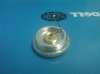
I was goiing to use a 1 Ohm 2 Watt Resistor, and a small ring of plastic.

Put the resistor in heat shrink tube and put one lead to the positive atty post and the other lead wraped around the other side of the plastic disk to touch the positive battery.

Here is a crappy pic of how I want to do it.

Any pointers if this will work would be nice.

Jason

/
 

Attachments

  • resistor mod.jpg
    resistor mod.jpg
    19.3 KB · Views: 88

petercro

Super Member
ECF Veteran
Dec 18, 2009
321
4
Brough East Yorkshire, UK
Jason
The Idea is sound.
A resistor will reduce the voltage to the atty, as it does when using it with an LED.
But remember this. A resistor does exactly what it is.
It resists the flow. In doing so it produces heat.
So before the battery can power the atty, the resistor is draining power from the battery reducing the time before its next charge.
So if you want to reduce the voltage on a battery use a MOSFET voltage regulator.
It is a great deal more efficient.
 

cpcp68

Senior Member
ECF Veteran
May 29, 2009
125
1
Knoxville, TN
My 2 cents.

if you have 6V source and a 3V atty, with a 1ohm resistor you are going to drop 4.5V on the atty, and the total current will be 6V/4ohm=1.5A so this works.
However, the power on the resistor will be 1ohm x (1.5 amp)^2=2.25W, so a bit over the resistor rating. Still sort of acceptable, although on long draws you may start smelling something.
Since this is all nominal and 6V is really more when the batteries are fully charged, I would increase the power rating of the resistor, to be on the safe side. But this is just me.

As a side note, a low dropout regulator would just keep constant the voltage on the atty, but the power it dissipates is still V*I, so it is not going to be more efficient than a resistor. The only way you can obtain more efficiency is to use a DC-DC converter that has good efficiency under this load (1.5~2A).
 

Jason365

Super Member
ECF Veteran
Aug 18, 2009
388
0
ATX
Ok, thanks for the reply..

I don't think I can get a volt regulator in the small area if have to work with. I got maybe 1/4 inch on each side of the battery connector.

Also with the volt regulator I would need to wire up more contacts, creating even less room.

But I will check it out.

Would the resistor get hot enough to melt plastic and damage the battery?
 

cpcp68

Senior Member
ECF Veteran
May 29, 2009
125
1
Knoxville, TN
I do not know what temperature the resistor will get and I quite frankly forgot how to calculate it. You can just try before you assemble things and see if it feels safe to you or just leave a piece o plastic on it and see what happens. You just have to replicate the conditions you have in your PV (atty about 3 ohm-- again it depends on the atty you have).

The battery should not suffer, unless you are draining more current than its rated discharge (in this case the battery will get hot independent of what your resistor does) or the resistor rests on the battery itself.

Also make sure you cannot accidentally turn your mod on in your pocket with an atty on.

Have I complicated the issue enough for you today? :)
 

Ralph T

Ultra Member
ECF Veteran
Dec 3, 2009
1,942
3,125
63
Albuquerque, NM
I do not know what temperature the resistor will get and I quite frankly forgot how to calculate it. You can just try before you assemble things and see if it feels safe to you or just leave a piece o plastic on it and see what happens. You just have to replicate the conditions you have in your PV (atty about 3 ohm-- again it depends on the atty you have).

The battery should not suffer, unless you are draining more current than its rated discharge (in this case the battery will get hot independent of what your resistor does) or the resistor rests on the battery itself.

Also make sure you cannot accidentally turn your mod on in your pocket with an atty on.

Have I complicated the issue enough for you today? :)

You also might consider using one or two diodes in place of the resistor, (thus in series with the atty and switch). Each diode will drop between .5 and .6 of a volt. This is also translated into lost heat, just like the resistor. So, two of these in series with your 6V battery will drop the voltage down to 4.8 to 5V. The 3 amp barrel diodes from rat shack might work. If not, the 6 amp ones would for sure.

Diodes are polarized and need to be connected in the right direction. Study this explanation. What you are aiming for is "forward bias".

Edit: Diodes capable of handling the heat seem a bit easier to come by than resistors of the same rating. The "wattage" rating of diodes is expressed in how much current or amperage the diode is rated for. So, assuming for instance that the diode drops .6V and is rated for 6 amperes current, then it is rated for... .6 V x 6 A = 3.6 Watts (the 3 amp ones, 1.8 Watts). The nice thing about a forward biased diode is that it will always drop that .6 volts and not a ratio of the overall voltage that a resistor does.
 
Last edited:

indyxlt

Senior Member
ECF Veteran
Verified Member
Oct 26, 2009
124
5
New England
Please forgive me, I don't mean to hijack this thread but.....I had an idea to easily add a resistor to a mod. I'm pretty stupid when it comes to electronics. I can wire a house, hook up an entertainment system but don't ask me to fix your radio. I can sort of figure out what's going on when you guys post schematics here.

I look at my GLV and see the resistor tucked up behind the battery contact by the switch and think "if that thing ever goes bad ( I don't know how rugged they are) I can't fix this myself". "Or, gee what would this be like at 6v?"

Anyway, I figured you guys could tell me why I'm all washed up.

Could you just sandwich a resistor, regulator, diode or whatever small component in between a couple metal slugs and add on top of the battery stack? Like each resistor lead is attached to a slug. The slug would be insulated from the casing around the edge. Yes there would have to be room for it inside the unit. The part would be able to be swapped out like a battery for repair or to use various voltages.

Please tell me what I'm missing (in layman's terms).

Thanks
 

Ralph T

Ultra Member
ECF Veteran
Dec 3, 2009
1,942
3,125
63
Albuquerque, NM
Please forgive me, I don't mean to hijack this thread but.....I had an idea to easily add a resistor to a mod. I'm pretty stupid when it comes to electronics. I can wire a house, hook up an entertainment system but don't ask me to fix your radio. I can sort of figure out what's going on when you guys post schematics here.

I look at my GLV and see the resistor tucked up behind the battery contact by the switch and think "if that thing ever goes bad ( I don't know how rugged they are) I can't fix this myself". "Or, gee what would this be like at 6v?"

Anyway, I figured you guys could tell me why I'm all washed up.

Could you just sandwich a resistor, regulator, diode or whatever small component in between a couple metal slugs and add on top of the battery stack? Like each resistor lead is attached to a slug. The slug would be insulated from the casing around the edge. Yes there would have to be room for it inside the unit. The part would be able to be swapped out like a battery for repair or to use various voltages.

Please tell me what I'm missing (in layman's terms).

Thanks

Actually, that's a capital idea. Make it modular. Something like a thick coin that is the diameter of the battery in question. You would have to use a resistor or diode(s) I do believe, because a regulator would be difficult (dimension-wise) to squeeze in there. Nice thinking!!!

Perhaps, instead of trying to fit it in the battery compartment it could be incorporated in these http://www.e-cigarette-forum.com/forum/battery-mods/25949-pvma-no-more-worries-batt-connectors.html
 
Last edited:

Wall

Senior Member
ECF Veteran
Sep 19, 2009
138
0
Racine, WI
I thought the resistor dropped the current not the voltage?

I = V/R The V being the "constant" from the battery and as R gets larger then I would be lower?

I know people use regulators or boosters to alter the voltage.

I mean in the example of a 510 with 2.5 ohm resistance to the atty, at V = 3.7 then I would be 3.7/2.5 = 1.5 A If you added a 1 ohm resister in series with the atty, then it would be additive and 3.7/3.5 = ~ 1amp.

Though if you use a higher voltage source and the battery cant supply the proper amps then the voltage would suffer?

Notice, lots of question marks because Im new to figuring out this electrical stuff :p
 

Wireguy

Super Member
ECF Veteran
Oct 24, 2009
932
1
Birmingham Al

cpcp68

Senior Member
ECF Veteran
May 29, 2009
125
1
Knoxville, TN
I thought the resistor dropped the current not the voltage?

I = V/R The V being the "constant" from the battery and as R gets larger then I would be lower?

I know people use regulators or boosters to alter the voltage.

I mean in the example of a 510 with 2.5 ohm resistance to the atty, at V = 3.7 then I would be 3.7/2.5 = 1.5 A If you added a 1 ohm resister in series with the atty, then it would be additive and 3.7/3.5 = ~ 1amp.

Though if you use a higher voltage source and the battery cant supply the proper amps then the voltage would suffer?

Notice, lots of question marks because Im new to figuring out this electrical stuff :p

some answers for you:

it is jargon. we say the current "flows" through a resistor and this creates a voltage "drop" across the resistor

you are right, with higher R, I is lower for the same V. i.e. less power to the atty. It looks like there is a sweet spot for certain attys at 5V (or ~10W of power), so people intentionally drop the voltage to the atty by introducing a series resistor. Others, will use a regulator (so the voltage to the atty remains constant while the battery voltage is high enough). Some people also (I made a schematic for this) use boosters to obtain 5V from a 3.7V 2.2Ah battery.

indeed, the voltage would suffer if the source cannot supply enough current. In the case of batteries, the battery would heat up as well (being drained over max current) and a protection circuit (for protected batteries would kick in). For unprotected batteries, there could be some problems.
 

Ralph T

Ultra Member
ECF Veteran
Dec 3, 2009
1,942
3,125
63
Albuquerque, NM
some answers for you:

it is jargon. we say the current "flows" through a resistor and this creates a voltage "drop" across the resistor

you are right, with higher R, I is lower for the same V. i.e. less power to the atty. It looks like there is a sweet spot for certain attys at 5V (or ~10W of power), so people intentionally drop the voltage to the atty by introducing a series resistor. Others, will use a regulator (so the voltage to the atty remains constant while the battery voltage is high enough). Some people also (I made a schematic for this) use boosters to obtain 5V from a 3.7V 2.2Ah battery.

indeed, the voltage would suffer if the source cannot supply enough current. In the case of batteries, the battery would heat up as well (being drained over max current) and a protection circuit (for protected batteries would kick in). For unprotected batteries, there could be some problems.

I, for one, would be very interested in seeing that!
 
Status
Not open for further replies.

Users who are viewing this thread