DNA 30 passthru project...

Status
Not open for further replies.

mamu

Ultra Member
ECF Veteran
Verified Member
Mar 29, 2009
2,551
1,523
IN USA
I found a few AC to DC power supplies that are suitable for use with a dna passthru mod I'm working on.

RS-75-3.3 is 0-15A, 3.3v (adjustable from 3.0v - 3.6v mine adjusted up to 3.7v).

pt1.jpg


Input voltage drop 0.23v running the DNA at 30W:
pt2.jpg


HSP-150-3.8 is 0-30A, 3.8v (adjustable from 3.4v - 4.2v mine adjusted up to 4.34 but turned it down to 4.2v).

pt3.jpg


Input voltage drop 0.13v running the DNA at 30W:
pt4.jpg


These power supplies will need to be enclosed in a protective case, so the search is on for one.

But now I have the decision what case I want to use for this project. No need to have space for batts woot! :laugh:
 

BJ43

Vaping Master
ECF Veteran
Verified Member
Nov 27, 2008
5,896
7,212
81
Love it... Ordered the power source.. Just a few points in my experience building many LM2596 passthrus in 2 and 3 AA boxes and round pill boxes.

Not too small as it makes them hard to hold and when the RBA gets hot it is uncomfortable.
The wire tether off the side so it can stand vertical.:)

BTW a source for the vehicle would be great. Have not found anything over 2 amps for my truck at 3.7/4.2V.

For higher amp 12v passthrus I have built, I have a 12v motorcycle battery on a trickle charger under my desk as the source.. :) I am now testing a raptor in my truck, hoping the 13.8v won't blow it.
 
Last edited:

mamu

Ultra Member
ECF Veteran
Verified Member
Mar 29, 2009
2,551
1,523
IN USA
ok... finally got my ducks in a row and got er done.

I spent a huge amount of time searching for high amp DC connectors and finally found Switchcraft's 11A jacks and plugs. They aint cheap either. :laugh: http://www.switchcraft.com/productsummary.aspx?Parent=1074

I had to nix the RS-75-3.3 MeanWell power supply - wasn't enough of a voltage cushion to account for the voltage drop under load with using a 3' DC power cord and DC connectors.

I found a looper case that fit the HSP-150-3.8 MeanWell power supply perfect. Total cost of assembly for this power supply (power supply, AC power cord, 3' 16AWG DC power cord, Switchcraft 11A DC connector, 10A on/off switch, looper case) ~95.00.

dpt1.jpg


So, while I was waiting for parts to come in, I decided to play with a 5V 10A power brick.
dpt2.jpg


The power brick I got metered at 5.6V. I pried it open and added 2x 16A diodes (FES16DT-E3/45) in series to drop the source voltage by at least 1V (metered at 4.5V - 4.6V). I mounted the diodes to the power brick's heat shield to use as a heat sink - works great and the diodes stay cool to the touch under load.
pt2-a-.jpg


I was getting a voltage drop under load at the watts I vape (15W) that brought the source voltage down to under 4.5V, so I removed 1 diode. If you vape lower watts, you'll need the 2 diodes to bring that source voltage down to less than 4.5V under load.

I replaced the power brick's DC connector with a Switchcraft connector. Total cost of assembly for the power brick (power brick, 2x diodes, Switchcraft 11A DC connector) ~45.

HSP-150-3.8 with 3' 16AWG DC cord and set of Switchcraft's 11A DC connectors...
Source voltage...
ps-01.jpg


Voltage drop @ 15W...
ps-02.jpg


Voltage drop @ 30W...
ps-03.jpg


5V 10A power brick with 3' 16AWG DC cord and set of Switchcraft's 11A DC connectors...
Source voltage with 1 diode...
ps-04.jpg


Voltage drop @ 15W...
ps-05.jpg


Voltage drop @ 30W...
ps-06.jpg


Now that the power supply was settled, I went on a search for a case and chose Hammond's 1455D601BU case (60mm x 45mm x 25mm).

All done...
dpt5.jpg


dpt6.jpg


dpt3.jpg


dpt4.jpg
 

ecat

Full Member
Oct 7, 2013
42
31
uk
Nice work as always Mamu :)

As you have discovered, the voltage dropped by a diode is dependent upon the current passing through the diode, as such, most (all?) diode datasheets will have a graph of voltage drop (usually called forward voltage, symbol Vf) against current. There is a way, theoretically a very simple way, to modify your power brick to deliver regulated 4V instead of 5V.

Switch mode power supplies constantly monitor the voltage they are delivering and change how long they are switched on to try to maintain the specified output voltage. It sounds complicated but in general, as the power supply is simply a slave to the voltage it is delivering, to reduce the regulated output voltage all you need to do is change the value of one or two resistors.

The explanation of how and what is a little involved, much more so than the actual modification. If you're interested I'll post details, otherwise enjoy the power of the diode and vape on :)

Obligatory Warnings:
Switch mode power supplies are home to dangerous voltages. Don't even think of taking one apart unless you understand and accept the risks and do not come back to haunt me or any connected to this forum should you ignore this warning.

Do not try to increase the output voltage of a switch mode power supply, some components will go bang!

Do not try the impossible and reduce the voltage by too much - not so much dangerous, just nasty.

Do not connect any of the switch mode outputs to the metal case of your pass through. It is easy to think 'I'll connect the 0V (zero) line to the case as an earth or for safety". DON'T. Assume the output of the switch mode 'floats', that is, there is no internal earth connection which means holding the case while touching any other mains appliance could result in a shock.

So long as the power brick has inspection certification (CE, UL, et.al.), the output (either positive or negative) should be sufficiently isolated from the power mains that it is inherently safe.
 
Last edited:

mamu

Ultra Member
ECF Veteran
Verified Member
Mar 29, 2009
2,551
1,523
IN USA
Thanks guys.

Now I need a matching blue drip tip to be fully color coordinated. :laugh:

...There is a way, theoretically a very simple way, to modify your power brick to deliver regulated 4V instead of 5V.

Switch mode power supplies constantly monitor the voltage they are delivering and change how long they are switched on to try to maintain the specified output voltage. It sounds complicated but in general, as the power supply is simply a slave to the voltage it is delivering, to reduce the regulated output voltage all you need to do is change the value of one or two resistors.

The explanation of how and what is a little involved, much more so than the actual modification. If you're interested I'll post details, otherwise enjoy the power of the diode and vape on :)

If it's a matter of simply changing a few onboard resisters, I definitely am interested, ecat. I have 2 other 5V 10A power bricks that also meter at 5.6V that need the voltage lowered.

Thanks!
 

ecat

Full Member
Oct 7, 2013
42
31
uk
My pleasure Mamu.

There's a lot of words in this post as I've tried to dot the i's and cross the t's but really there is not much to it. Feel free to ask if anything is not clear.

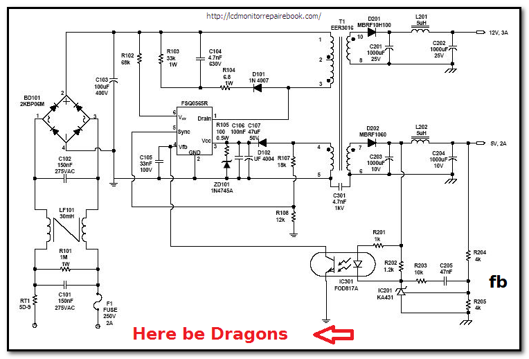
This is the schematic of a typical switch mode power supply (smps). Yours may not be exactly like this and certainly the names and values of the components will be different but the basic principle is most likely the same.

Bettersmps-schematic.png


Firstly, beware of everything to the left of T1, the voltages there are dangerous. Even when power is removed that pesky capacitor C103 may be holding a nasty surprise.

On to the good bit:

The output of this supply is 5V, we can ignore the upper 12V part because it doesn't exist on your supply, the low voltage cable would connect to 5V and ground (0V).

As you look down the right hand side of the schematic you can see +5V line connects to resistor R204 and then through R205 to ground, we'll call these resistors Rt for R204 the top one and Rb for R205 the bottom one. Two resistors in series like this are known as a 'voltage divider', the voltage that appears where Rt and Rb connect to each other, marked with 'fb' above, is 5V divided by the ratio of the two.

The voltage at Vfb = (Vout / (Rt + Rb)) * Rb = (5V / (4k + 4k)) * 4k = 2.5V

What we need to do is change either or both Rt and Rb such that whatever voltage we want out appears as 2.5V were the two resistors join.

For your smps you need to locate this voltage divider, two resister near the output cable that join to each other and connect to the output +ve and 0v. There is not usually very much going on at the output of a simple smps so I think your chances are good.

Measure the output voltage.
Measure the voltage where the two resistors join.
Unsolder one end of each of the two resistors you have identified, we need to unsolder at least one end so we can...
Measure the resistance of the two resistors.

Remembering the voltage divider equation above, do the maths and double check that the calculated Vfb voltage is the same as the measured Vfb voltage (it will probably be around 1V to 2.5V). If you are within about 0.2V you probably have the correct resistors.

if Vfb = (( Vout / (Rt + Rb)) * Rb an you now know the value of Vfb you can calculate a new value of, say, Rt to give you the output voltage you require.

Rt = ((Vout - Vfb) * Rb) / Vfb

In this example, we want 4V out and changing 5V to 4V is not a big enough change to cause concern. Both Rt and Rb measure as 4k ohms and our measured and double checked Vfb = 2.5V

Rt = ((4V - 2.5V) * 4k) / 2.5V
Rt = 2.4k ohms

2.4k is quite a large change from the existing 4k but this shouldn't cause any problems. You would pick a standard resistor with a value as close to the calculated value as possible. Higher values of Rt increase the output voltage, lower values of Rt decrease the output voltage.

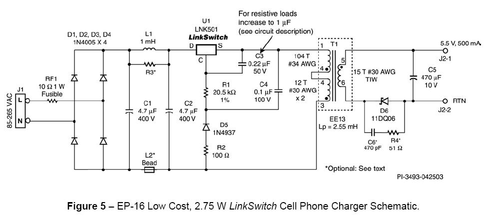
Now, if you are very unlucky and your smps does not use a voltage divider, looking something like this perhaps...

dak_16a_schematic_with_lnk501.jpg


then, unless you can hand draw a schematic for me, it's back to the diodes I'm afraid :(
 

Visus

Ultra Member
ECF Veteran
Jun 4, 2013
1,598
851
54
United States
Mamu another great tutorial.
One thing, IMO, coming out the side gets annoying if using daily. I use my passthru 95% of the time, 1st was side cable mount, I hated it..
My case has a pinching grommet on the bottom makes it easy to vape lefty or righty lining up dripping atty airholes so no drip on me lol. Wish I would have used a connector for swapping head units or using in car. Meh Ill get round to it eventually..

Ecat well why wouldn't it work like an OKR or Ti switching module :laugh: duh, thats outstanding; I also need to cut power down on my passthru and thought Mamu's way was awesome now whoa thats stellar informations.. I have resistors up the wazzoo, no diodes-- need to start asking questions. :laugh:
 

mamu

Ultra Member
ECF Veteran
Verified Member
Mar 29, 2009
2,551
1,523
IN USA
oh.my.gosh!! ecat I could totally give you a mega hug for sharing this quick and easy way to lower the source voltage from a power supply.

Thank you thank you thank you!!

I calculated I needed a 4K resistor for R18 in my power supply. I only had a 3.9K on hand so used that. I was shooting for 4.5V and got 4.4V. woohoo I'll take it!! :laugh:

original source voltage 5.6V...
ps1.jpg


R18 (6.2K) and R19 (5K)... voltage where the resistors join = 2.5V
psa.jpg


replaced R18 with a 3.9K resistor... voltage where the resistors join = 2.49V
psb.jpg


source voltage 4.4V...
ps2.jpg
 
Last edited:

ecat

Full Member
Oct 7, 2013
42
31
uk
You go girl :)

Excellent news and great work finding those two resistors. I wouldn't share this mod with just anyone but I knew you were up to the challenge. Still, let me reiterate:

Switch mode power supplies are very dangerous things to play with.
High voltage in parts, the capacitors hold this voltage even when disconnected from the mains, the heatsinks are sometimes live etc. If anyone else tries this then please be aware of the risks, accept the dangers and do not blame anyone else if something, or someone, goes up in smoke.

Mamu another great tutorial.
Ecat well why wouldn't it work like an OKR or Ti switching module duh, thats outstanding; I also need to cut power down on my passthru and thought Mamu's way was awesome now whoa thats stellar informations.. I have resistors up the wazzoo, no diodes-- need to start asking questions.

If you accept responsibility for the risks involved then ask the questions :)

Is there supposed to be a diagram in ecat's post? If so I cant see it :D

Too many words? lol
Well, I had to do something to frighten away the Darwin award candidates - sheesh I even included some mathematics ;)
 
Last edited:
Status
Not open for further replies.

Users who are viewing this thread