help with parallel triple 18650 mod schematic

Status
Not open for further replies.

Kurt0402

Ultra Member
Aug 26, 2015
1,483
2,676
27
Australia
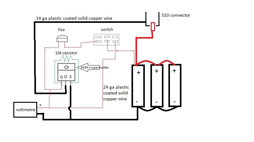
hi guys, so after doing some research i have come up with the design shown for a triple 18650 parallel mod, im pretty sure its fine apart from the switch, i want the colt meter to be on while holding the fire button, or whilst the switch is in the second "on" position, im confident this will work in the second on position, but not sure about it only coming on when fired when the switch is in the ready to fire position?
would be awesome if you could let me know if ive made any big mistake or if im completely wrong, or if there is a better way to achieve what i want
cheers guys :)
 

Kurt0402

Ultra Member
Aug 26, 2015
1,483
2,676
27
Australia
i was thinking and i feel like for what i want to work i may have to connect the positive voltmeter terminal in between the gate of the mosfet an the fire button, because in the way that is wired up im pretty sure the voltmeter will always be on when it is in the on (ready to fire) position
shown below;

 
Last edited:

Kurt0402

Ultra Member
Aug 26, 2015
1,483
2,676
27
Australia
The second one is wrong. You are running power to the gate via volt meter feed when the switch is in the off position. It will always fire in that position. It bypasses the switch. You first design will not autofire. I'm not sure why you don't like it. The meter is always on
ah i see what you mean, how would i wire it to have the meter on only when fired, i just want to be able t put it down and not have the display on all the time but not have to turn it off
 

Kurt0402

Ultra Member
Aug 26, 2015
1,483
2,676
27
Australia
The second drawing is what you are after from your description. That way you can check the batteries without arming the mod. I would highly suggest one of these on each battery just for safety. http://www.mouser.com/ProductDetail/TE-Connectivity/MHP-TA15-9-77/?qs=/ha2pyFadugw3UY4%2bk6FyTRt5VcAhouYP%2bPoptwCuCrPM4wVe6lAEg==
was going to install these, but i thought about it and im never going to be installing coils below 0.07 ish, and with fully charged batteries that would be the lowest for even 20 amp continous discharge, and i will be using (suposedly) 30 amp continuous discharge batteries, so long as im always sure of my readings and do my calcs i dont see the need for the added voltage drop across fuses
 
  • Like
Reactions: Izan

Kurt0402

Ultra Member
Aug 26, 2015
1,483
2,676
27
Australia
if i wire from between the gate and fire switch, to the top centre pin of the switch and then connect the positive voltmeter terminal to the top left pin on the switch, this will do what i want wont it ? not 100% certain on the working of switches but im certain that would work

:thumbs: ;)
Voltage drop is an issue on a multiple battery regulated device? Are you sure?
Personally... I'd spend the $5.00 on the fuses.
It's FAR too easy to put ANY battery in upside down/reversed.

Be safe

I
thanks for the comment, the way i saw it, because its a parallel device, with such high amperage, that means a larger voltage drop over a smaller resistance then the more batteries in a parallel device, the larger voltage drop over the fuse, because their is no change in voltage only current
also, it isnt regulated, only has a voltmeter no controls
 

dc99

Vaping Master
ECF Veteran
Verified Member
Aug 17, 2014
3,086
9,571
earth
The second one is wrong. You are running power to the gate via volt meter feed when the switch is in the off position. It will always fire in that position. It bypasses the switch. You first design will not autofire. I'm not sure why you don't like it. The meter is always on
Totally correct. I didn't see the wire going to the gate. Oops.
The fuses aren't to protect the mod, they are there to protect the batteries but its your choice. Those fuses get really close to 30 before they trip. That's close to 90.
 
Status
Not open for further replies.

Users who are viewing this thread