Hi there, I´m into my 3rd month free from analogs and after the 'ego' phase I started to upgrade my gear and some doubts start to happen when leaping into new diy grounds.
Maybe this is not a very good issue for a new members section but here it goes:
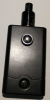
I'm have a Vamo v6 pcb chip ordered by mistake laying around and decided to build myself a mod. Just bought this case USB Power Bank 3X 18650 Battery Charger Box w LED Light for Cell Phone iPod MP3 | eBay and
have a momentary 12mm button from a coffe machine that will work nicely but need some tips on a couple of issues:
I don't feel comfortable to solder on the small button leads, any tips on what to use to make them work? Somebody mentioned that rivet heads would be a good thing to work with as an extension... But how?
Also, how can I fix the pcb to the case safely? Make some hot glue mess to give some height an then fix it there with more hot glue(is it safe)? It has no mounting points, after all it's designed to slide into a tube!
Any tips will be welcome. Or maybe I'll end up just attaching the 12mm button, throw the pcb inside the case and deal with opening the cover everytime I need some other buttons clicked.
Maybe this is not a very good issue for a new members section but here it goes:
I'm have a Vamo v6 pcb chip ordered by mistake laying around and decided to build myself a mod. Just bought this case USB Power Bank 3X 18650 Battery Charger Box w LED Light for Cell Phone iPod MP3 | eBay and
have a momentary 12mm button from a coffe machine that will work nicely but need some tips on a couple of issues:
I don't feel comfortable to solder on the small button leads, any tips on what to use to make them work? Somebody mentioned that rivet heads would be a good thing to work with as an extension... But how?
Also, how can I fix the pcb to the case safely? Make some hot glue mess to give some height an then fix it there with more hot glue(is it safe)? It has no mounting points, after all it's designed to slide into a tube!
Any tips will be welcome. Or maybe I'll end up just attaching the 12mm button, throw the pcb inside the case and deal with opening the cover everytime I need some other buttons clicked.
")