
Next one nearly ready for hardware and electronics to go in.
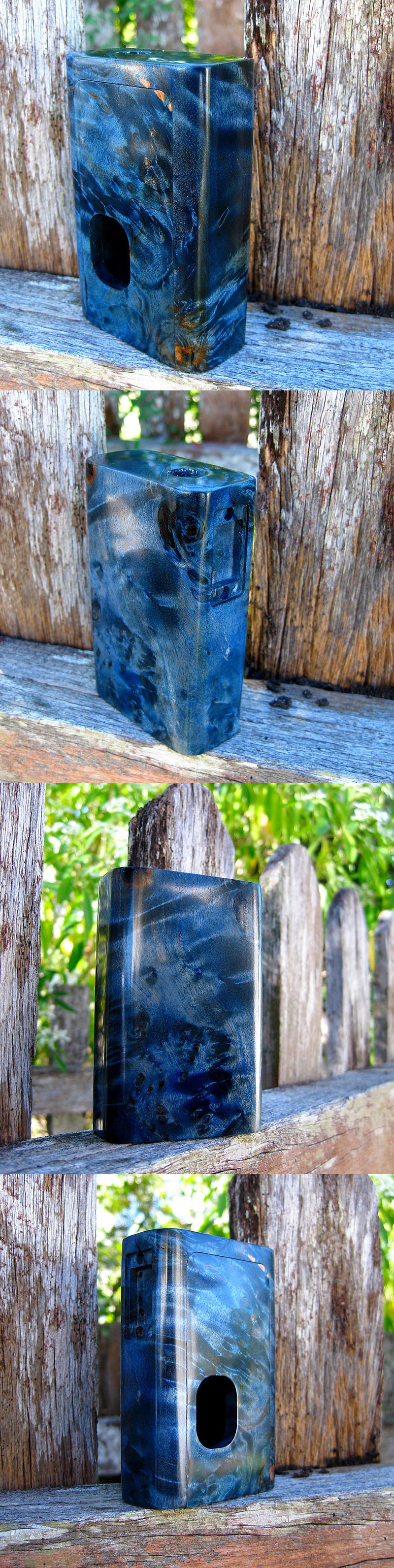
And using the sun to show off the holographic grain.
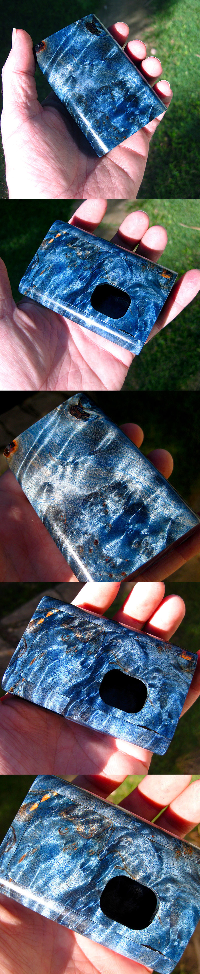
Wow! Gorgeous.
Next one nearly ready for hardware and electronics to go in.
And using the sun to show off the holographic grain.
Are you talking about that little brass sleeve thing?I messed with one of those for a few days and never did get it figured out.I tried pinching it together,spreading it apart,everything haha.Anyone have any tips for soldering the FDV positive connection to the positive pin. Cannot get it solid.....
Am I suppose to pinch it or something seriously frustrated...
FDA BOC
I never did get it good and snug,but what i ended up doing was using a screwdriver to spread the 2 parts apart where the gap is,which tightened it up a little bit,and then got some solder to stick to that brass part and it sort of wedged it there.If i twisted it i could move it,so i'm sure i had some voltage drop,but it seemed to work ok.I still have that mod,and it still works fine that way 6 months later.Just make sure to get a good solder connection where you insert the wire into the back of it.Yes. I've just finished the sub-ohmies conversion and this is stopping me from enjoying things....I hope anyway this is the only thing
FDA BOC
Yeah the wire connection is solid. Spreading them worked better huh?I never did get it good and snug,but what i ended up doing was using a screwdriver to spread the 2 parts apart where the gap is,which tightened it up a little bit,and then got some solder to stick to that brass part and it sort of wedged it there.If i twisted it i could move it,so i'm sure i had some voltage drop,but it seemed to work ok.I still have that mod,and it still works fine that way 6 months later.Just make sure to get a good solder connection where you insert the wire into the back of it.
It may work better pinching them,i just got fed up and tired of fighting it,so spreading them gave me room to squueze a small amount of solder between the brass and the stainless tube.In his listing,fd says to spread them,but for me it did nothing at all really,it still slid up and down,and i was afraid to spread it any farther than i did because i figured it would break.Yeah the wire connection is solid. Spreading them worked better huh?
I was going to pinch them together....
Going to think about it for a bit....
Thanks
FDA BOC
Looking at set screw collars just not sure what size....It may work better pinching them,i just got fed up and tired of fighting it,so spreading them gave me room to squueze a small amount of solder between the brass and the stainless tube.In his listing,fd says to spread them,but for me it did nothing at all really,it still slid up and down,and i was afraid to spread it any farther than i did because i figured it would break.
If you get a good solution figured out,please post it up.I have another mod i am getting ready to convert here soon,and i have some of the brass bottom feed cores,but would like to use the stainless,but i won't go through that pita again that i did the last time haha.
Yeah, seriously like 3 hours trying to get a decent connection. Horrendous. My soldering skills are bad but, not that bad. I'll have to order some of the hobby ones. Don't have either of those items.I make my own set screw collars out of a piece of bass rod, just drill a center hole large enough for the needle to pass through then drill a hole across from the side and tap it for a set screw. real easy and makes a great solid connection direct to the ss needle. I never even use the fat daddy brass part at all
I make my own set screw collars out of a piece of bass rod, just drill a center hole large enough for the needle to pass through then drill a hole across from the side and tap it for a set screw. real easy and makes a great solid connection direct to the ss needle. I never even use the fat daddy brass part at all
I know this is a lil off topic but this thread has all the seasoned modders in it.... i seen a few old school dna boards wired with multiple batteries, 3 to be exact.
How is that possible without damaging the board and going above the boards working voltage?
I understand that wiring the batts in series is out the question. Would i have to wire batts in parallel?
Here's the thing i want to wire a 150w board thats uses 2 batterys and an 8.4V to work. I want to wire this board with 3 18650s.
Is it possible and how would i do it?
Anyone have any tips for soldering the FDV positive connection to the positive pin. Cannot get it solid.....
Am I suppose to pinch it or something seriously frustrated...
FDA BOC
Thanks. I figured as much seeing some of the videos. Used a v5 and I'm not sure it's removable. Baked ceramic. I could totally be wrong too. Apparently torching could possibly cause the pin pop out.We use to remove the center/positive pin and then drop in a small piece of solder into the hole and then heat it with a butane/cigarette lighter for a few seconds
and then insert the wire into the open hole with the molten solder and let it cool for a few seconds and then reinsert the center pin back into the housing.....seem
to work pretty good for a lot of people............if you are trying to solder a metal tube into
your connector then you must use flux and sand the surfaces with fine sand paper good and clean before you start and then wipe solder iron clean before starting.....
Its made to be ran with 2 18650 batteries according to supplyer.. 8.2v to operate the board.Batteries is series increase voltage, so a 3s configuration delivers 3x4.2V = 12.6V and you would need the regulator to step it down to whatever you want to drive at that regulated voltage.
Batteries in parallel increases capacity, so a 3p configuration and a single cell with 2000mAh capacity will deliver 3x2000mAh = 6000mAh. This also triples your power output. In other words 3 times the maximum amperage the single cell can safely deliver. That value is usually given in "C", so a single 5C battery cell can deliver 5x2000mA = 10 Ampere.
The 150 Watt you mentioned is most likely what the board can deliver, without going up in flames. what you need to know is what the maximum input regulator can take. I doubt it will tolerate a 3s configuration, but will have no trouble with a 2s2p configuration.
HTH
Cheers.
Thank you SubOhmies and Laurie 9300. I didn't realize you were a member here.
View attachment 558743 View attachment 558745 View attachment 558747
FDA BOC
Thanks man. Huge help. Holy cra.ptastic...I finally figured out how to solder. I couldn't believe I could be so bad at something. I'm still not good at it but, I can do it satisfactorily.Well done mate[emoji1303][emoji1303]
Looks clean
