Very easy vv mod w/ switching regulator

Status
Not open for further replies.

illuxion

Senior Member
ECF Veteran
Verified Member
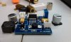
yeah, I ran across that page also. I don't think I'll use an input cap as the battery is essentially a cap itself and the output cap I'll just remove the one they did and replace it with a big tantalum cap so that the adj pin sees a relatively stable V. I can't tell what they said to short, but I'll see when I get the modules. They are .82" x .82" x .27" so should be pretty easy to fit anywhere.

LM2596s are great devices and I actually spotted some in Fry's today off the shelf, but for the cost of these modules on ebay, we can't go wrong.

As soon as I get mine in I'll have a few freebies to give out(for shipping cost only) for folks to play with, no way I'm using 10 of them lol. I already got shipment notification so we'll see how long it takes. When they come in I'll beat them up on the bench to see what they can do.
 

illuxion

Senior Member
ECF Veteran
Verified Member
I got the 2596 boards in today. 1 will be sacrificed tomorrow to see how small I can get everything. Since the back is just a tinned plate I'll probably use a blade to notch it just enough to mount the schottky and replace the monster electrolytics with some smd tantalum on the backside, move Cff(c3) in a little closer and put some leads on the pot so I can put it where I want. I should be able to cut the board in front of the inductor, and as close as possible on either side of the chip and inductor then get it down to 34 x 18 x 15 deep. right now its 38 x 38 x 10. Hmmm maybe put a layer of conformal coat over the chip then super glue the caps in front of the inductor, then I'll still be at 10 deep. I wonder if I can find a smaller inductor also.

I also noticed, if you put the board so you can read it, the board number in the lower right, look right in front of the inductor. I believe that is the is the enable pin shorted to ground(I'll verify tomorrow). If you use this module, I'd put a 200k resistor between pins 1 and 5 then you can use a microswitch between pin 5 and and ground to trigger the output, and you'll have very little current going through the switch. Put a big switch coming off the battery as your master.

I'm looking to use 2 10440s, the hacked module, and an on LED in as small of a box as possible. I'll cut and glue my own plastic if I have to. :p First mod is tiny and reasonably strong, second mod will be a bottom feeder with LED display and the meanest 18650s I can find :D
 
Last edited:

illuxion

Senior Member
ECF Veteran
Verified Member
How low does this OP's board go down to?

The one mamu used and that I have several of shows the following.

with 1k ohm, so I'm loading it, but not too much.

It shows very good saturation.

min 3.15V(won't regulate below this)
@ 3.15v in min 1.23v max 2.57 out

I didn't test up to high but

8v in min 1.23 max 7.36 out

now with a real load 2.5ohm 10w resistor

with 7.20v input 5.00v output with no load, it then sags to 4.84v with 2.5ohm load showing 1.78A Decreasing the input voltage to about 6.4v in the output voltage starts to sag, around 6v the current starts to sag pretty hard. Shorting the load it gets up to about 2.5A, then folds back to about 1.3A and holds 1.3A getting barely warm(short circuit protection maybe?). With 1ohm load it current limits something over what my supply will do, something over 3A and holds it there for a while, but the chip started getting a tad warm after about a minute so I turned it off. I doubt anyone would have a 1ohm atty and try to vape it with 5V so we're safe.

Let me know if there is something else you want me to look at, another voltage or something

oh and opening the short in front of the inductor doesn't do anything, at least on the board I played with today.
 
Last edited:

WillyB

Vaping Master
ECF Veteran
Oct 21, 2009
3,709
591
USA
Thanks that helps, so if I was to use 2- 3.6v batteries, I'd get a min of 1.23v. I was wondering how low it goes for the new cartos. Seems like even 3v is too hot for some of them.
Following Mamu's original link for her board you'll see:
# Input Voltage: 3-30VDC.
# Output voltage: 1.3-18VDC.
# Max output current: 3A.
 

illuxion

Senior Member
ECF Veteran
Verified Member
Thanks that helps, so if I was to use 2- 3.6v batteries, I'd get a min of 1.23v. I was wondering how low it goes for the new cartos. Seems like even 3v is too hot for some of them.

I tested at 7.2v to simulate 2 3.6v batteries, although they are closer to 4v each when charged. Once you set the output voltage it stays until the batteries get too close to the output voltage. It looks like about 3/4 of a volt away then it starts to collapse. If you have 2 fully charged 3.6v batteries, you'll be able to adjust anywhere from 1.25v up to about 7.25v and everywhere in between, it's a very nice little module.
 

illuxion

Senior Member
ECF Veteran
Verified Member
changed the caps to tantalum smd, and changed the coil to 22uh 2.2a,looking at the datasheet it's fine as I won't be using higher voltage and the current is fine. Tested it with 901 atty and 510 cart and works like a champ.
 

Attachments

  • IMAG0216.jpg
    IMAG0216.jpg
    18.9 KB · Views: 223

illuxion

Senior Member
ECF Veteran
Verified Member
Ok more tinkering.

Here is the BOM:
IC1 LM2596s-ADJ
C1 220uf 10v tantalum (was 220uf 35v elec)
C2 220uf 10v tantalum (was 470uf 35v elec)
C3(cff) 100nf tantalum(was 100nf ceramic SMD, measured 95nf)
D1 3A 35V schottky
L1 22uh 2.2a(was 100uh 5a)
R1 1.5kohm (was 1.5kohm smd)
W1(R2) 20kohm 12 turn pot

I'm just waiting for my case to come in so that I can decide how I want the pot. C3 will be mounted to the legs of the Pot, R1 is hiding underneath the board. When I'm done I'll cut off the extra board, but it's nice leverage for now. I'll also probably conformal coat it, or possibly potting compound for heat dispersion. It should measure 16 x 25 x 7, a little better than the 38x38x18 that is started as lol. A 9v battery is about 25x16x48, so this should fit in a 9v on top of a pair of 10440s since they are 10x43 and the 9v case at mad vapes has some room to spare on top.

a VV mod with 901 and 510 connectors(not enough current to dual vape, but one or the other is fine lol) and $5 for batteries slightly bigger than a 9v battery woohoo. Lets see, $2 box, $5 batteries, $5 for 2 connectors, $7 for regulator board. $19 and a little time, not bad. Granted the tantalum caps and inductor cost more than that, but I git em for free :D
 

Attachments

  • IMAG0221.jpg
    IMAG0221.jpg
    17.5 KB · Views: 187

Para

Ultra Member
ECF Veteran
Verified Member
Aug 15, 2010
2,812
1,180
Texas
If you remove the 2 bottom screw posts and lowered everything, then the voltage reader would fit and the board wouldn't be in the way of the atty and switch.

Awesome mod and can't wait to start mine. I just got a handful of volt readers in the mail so I'm gonna try and mod the box to add that to mine.

Thanks again for a great find and tutorial
 

misterD

Ultra Member
ECF Veteran
Verified Member
Dec 27, 2009
2,632
653
worster - crappychusetts
Awesome mod and can't wait to start mine. I just got a handful of volt readers in the mail so I'm gonna try and mod the box to add that to mine.

Thanks again for a great find and tutorial

lets see who finishes first? (your dog is blinking at me! is he gonna atack?) :lol:
 

illuxion

Senior Member
ECF Veteran
Verified Member
Hmm.

A little DIY can make it to an adjustable Step-down Power Supply Module: Just take a few steps as show in the following picture.
Input: 4.75-23V
Output: 0.9-22V


MP2307DN.jpg


I was also looking at this one, LM2596 based, to see if I can squeeze a juice bottle in without resorting to a wide enclosure. It's about 1.7 X .8". Mamu's is actually closer to 1.5 X 1.5".
12811962680.jpg


I got this one for $3 shipped (he has no more), it's about 1 5/8 X 1 1/4" (can't find my metric ruler).

I got the little guys in on saturday but the rest of my stuff was at work, so had to wait for today to play with them. They are about 7/8" x 7/8" x 5/16" in the case and 11/16 x 11/16 x 1/4"(18mmx18mmx5mm) without the case not considering the leads.

These little things are pretty stable as is. I shorted the little resistor on top put a pot there and it's a happy camper, no huge input and output caps. Using a switching bench suppy with some pretty dirty 8v input this thing was spitting out 4.5v with about 25mv ripple, not bad to me. I put a 2ohm load on it for 15 minutes and it was barely warm, I'd say about 90°F(I'll bring my non contact thermometer when I get back from vacation). This was without the case on it, so worst case. The ripple got pretty big with the load on it, but the atty doesn't care about ripple. With 8v in and 4.5v out it would do 5A, but the chip started getting pretty warm.

Here's some pics of just how tiny they are.

The height difference out of it's case.
little1.jpg


there's one hiding under the batteries in the 9v case with two 10440s on top, and the 4AAA box looks like it will fit the regulator and the voltmeter. I just need to scrounge some LDOs for LEDs and I'm set. both will have an on LED and a vaping LED. I looked at putting in a voltage supervisor and an LED in the small one but too much extra crap needed.
little2.jpg


$10 for 10 and took about 2 weeks to get here, not bad at all. Only need to pick up pots and you're set. I'll do my own thread and stop hogging other folks when I get these done :p
 
Last edited:
Status
Not open for further replies.

Users who are viewing this thread