2 questions.

Status
Not open for further replies.

Bahnzo

Unregistered Supplier
ECF Veteran
Jul 21, 2010
825
77
55
Colorado
Another couple questions: it seems one of these mods I built (the small one, with a single 10440) doesn't vape as well as my Riva. The Riva easily outputs more vapor with the same atty. I assume this is due to voltage? Could this be because I suck at soldering and therefore the wires are causing a loss in resistance?

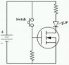
Also, the switch seems kind of touchy. I checked the connections with a meter and they all seem solid, so could it be the switch itself? When I say touchy I mean it doesn't always fire, or I need to press it slow to get it to fire.

Finally, I built a 5v box using the directions on the madvapes site. One thing that tutorial didn't cover was how to install a LED with the perfboard (is that what it's called? the 5x4 board you solder connections to). Is there something that describes how this is done?

Thanks.
 
Last edited:

duby

Senior Member
ECF Veteran
Verified Member
May 9, 2010
203
2
atlanta
Alright, I'll try to answer as much as I can.
First off, earlier you asked about buying switches.
digikey.com
Allelectronics.com
Radioshack
Fry's Electronics
Some hobby stores.

10440 mod question:
10440 mods kinda suck IMO. The batteries are only rated around 350mah. The ego is rated at 650mah or 600. Particularly with an LR atty you're going to pulling too much current out of a 10440. The battery compensates by dropping the voltage and adding an internal resistance. IMR batteries can make up for this since they have lower internal resistance and can support higher drain rates.

Poor solder joints can cause additional resistance yes. You can measure this using your multimeter(Do you have one?). Though I sincerely doubt this is the issue. LR attys need bigger batteries. 10440 and LR atty is just a combo that will fail.

Switches: Sometimes there are defects in manufactured switches. There are parts inside that can malfunction or break if you drop them. If I think the switch is the issue I take a wire, screwdriver, keys, tweezers, etc.(something conductive) and short out across the switch to see if it fires without issue. You can use the master on/off instead of the switch this way to see if it vapes better as well.

If you used the instructions I am thinking of, you should have only one lead soldered to the Vout pin. Solder a wire to the Vout, attach an LED and Resistor in series then solder the other end of the LED/resistor to the ground.
 

Brad-c

Moved On
ECF Veteran
Jul 5, 2010
153
0
hawaii,puna
Well.... I wouldn't suggest you get any of these near water... don't surf with em dude! The atties are not water proof even if the battery box is sealed!

EDIT:


P.S. Brad-C Hope we don't have that drought soon... but stocking up seems like a wise thing to do!

Hope Everyone's mods go well!


Lol.. i just didnt know what to use as a signature.. plus i live in hawaii so if the tug boats go on strike i will survive... atleast for vaping purposes..
 

Bahnzo

Unregistered Supplier
ECF Veteran
Jul 21, 2010
825
77
55
Colorado
Alright, so I've succeeded in building a few boxes with thanks to all here. Now I want to go a step further....

I really want to use a tactile switch, the standard switches I find a bit large. From what I've read, the best way to make sure the tact switches last is to use a mosfet. I've done some reading and searching and my main question is how to go about wiring one up. I found this diagram:
mos4.gif


So let me try to understand and someone please jump in when I prove myself wrong here....you would wire the ground from the battery to the source(and the atty ground), and the drain to a 10k ohm resister and then to the atty positive. The gate is essentially the switch, so positive from the battery, to the switch to the gate. Is that right???
 

bigblue30

Super Member
ECF Veteran
Alright, so I've succeeded in building a few boxes with thanks to all here. Now I want to go a step further....

I really want to use a tactile switch, the standard switches I find a bit large. From what I've read, the best way to make sure the tact switches last is to use a mosfet. I've done some reading and searching and my main question is how to go about wiring one up. I found this diagram:
mos4.gif


So let me try to understand and someone please jump in when I prove myself wrong here....you would wire the ground from the battery to the source(and the atty ground), and the drain to a 10k ohm resister and then to the atty positive. The gate is essentially the switch, so positive from the battery, to the switch to the gate. Is that right???

The picture below is the first one I could find....You would replace the LED and resistor with the addy. OR you could parallel the LED and atty and you would have a "fire" LED.

The LED Resistor would be around 220-400 ohms and the gate resistor would be 10k.
 

Attachments

  • Mosfet_n-ch_circuit.jpg
    Mosfet_n-ch_circuit.jpg
    9.2 KB · Views: 17

WillyB

Vaping Master
ECF Veteran
Oct 21, 2009
3,709
591
USA
Alright, so I've succeeded in building a few boxes with thanks to all here. Now I want to go a step further....

I really want to use a tactile switch, the standard switches I find a bit large. From what I've read, the best way to make sure the tact switches last is to use a mosfet. I've done some reading and searching and my main question is how to go about wiring one up. I found this diagram:

So let me try to understand and someone please jump in when I prove myself wrong here....you would wire the ground from the battery to the source(and the atty ground), and the drain to a 10k ohm resister and then to the atty positive. The gate is essentially the switch, so positive from the battery, to the switch to the gate. Is that right???
I don't know which switch you want to use, but there is more than just current to be concerned with. Most of these 'tact' switches aren't meant to be used with the kind of constant action we use. They are cheap and cheaply made with inferior construction in general. No matter how you choose to wire it a 60¢ switch will always be made with 5¢ worth of material.

you would wire the ground from the battery to the source(and the atty ground), and the drain to a 10k ohm resister and then to the atty positive.
Atties have no polarity. MOSFETs always switch the negative leg. Your question is confusing.

Which ever part of the atty connector the drain goes to, the positive lead will go to the other.
 

Bahnzo

Unregistered Supplier
ECF Veteran
Jul 21, 2010
825
77
55
Colorado
Atties have no polarity. MOSFETs always switch the negative leg. Your question is confusing.

Which ever part of the atty connector the drain goes to, the positive lead will go to the other.

So you would then connect the drain to the center post on the atty connector and the positive to the "shell" of the atty? I just assumed the post was positive because every other tutorial I've read shows the positive going to the post.
 

Bahnzo

Unregistered Supplier
ECF Veteran
Jul 21, 2010
825
77
55
Colorado
The picture below is the first one I could find....You would replace the LED and resistor with the addy. OR you could parallel the LED and atty and you would have a "fire" LED.

The LED Resistor would be around 220-400 ohms and the gate resistor would be 10k.

Thanks, I need to learn to read schematics I guess.
 

bigblue30

Super Member
ECF Veteran
So you would then connect the drain to the center post on the atty connector and the positive to the "shell" of the atty? I just assumed the post was positive because every other tutorial I've read shows the positive going to the post.

If you wanted to do it that way..and that is OK....The drain would go to the "shell" and the center post would go back to the positive battery.
 

Bahnzo

Unregistered Supplier
ECF Veteran
Jul 21, 2010
825
77
55
Colorado
If you wanted to do it that way..and that is OK....The drain would go to the "shell" and the center post would go back to the positive battery.

Alright, so am I to infer that it doesn't really matter what goes where on the atty, as long as one goes to the post and one to the shell?
 

WillyB

Vaping Master
ECF Veteran
Oct 21, 2009
3,709
591
USA
So you would then connect the drain to the center post on the atty connector and the positive to the "shell" of the atty? I just assumed the post was positive because every other tutorial I've read shows the positive going to the post.
On the basic box mods I make the box kill switch is on the negative. So that wire goes to my switch then to the connector's center post. The positive battery post goes to the shell, they are right next to each other (both short, straight shots).

If you were to build a copper pipe or flashlight mod with a pressed in (with continuity to the shell) connector and wanted to use a mosfet you would flip the battery so the shell is now positive. The mosfet's drain would now go to the center of the connector. Caesar's Precious seems to use this approach.
 

Bahnzo

Unregistered Supplier
ECF Veteran
Jul 21, 2010
825
77
55
Colorado
On the basic box mods I make the box kill switch is on the negative. So that wire goes to my switch then to the connector's center post. The positive battery post goes to the shell, they are right next to each other (both short, straight shots).

On the ones I've built (from the various tutorials here) I've always taken the kill switch (negative) straight to the shell, and the positive to the switch, then center post. So either works then?

Edit: so from further reading I can see it doesn't matter which one you switch with. I guess that's what kinda threw me off with the MOSFET, it has to use the negative to switch, which was opposite from what I was used to. Thanks.
 
Last edited:
Status
Not open for further replies.

Users who are viewing this thread