555 and FET PWM power controller MOD

Status
Not open for further replies.

Dragon@HEC

Full Member
ECF Veteran
Jul 20, 2009
31
0
heckaizou.blogspot.com
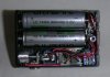
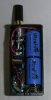
Ladies and gentlemen, nice to meet you.

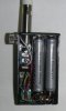
I am a person who is making an electronic cigarette mod in Japan.
This time, I will report because I made mod equipped with the power controller.
A simple circuit of the chopper control that combines timer IC555 and power FET is used.
The schematic diagram and animation, etc. are prepared, and visit interesting one by all means, please.

modranaito.blogspot.com/2010/03/mod.html

Please already pardon it when it is a method of someone's design though information on similar MOD was not able to be confirmed by the article on this forum.

I am not so good at English though it refuses beforehand.
Please choose a simple word when you send the comment and the question.

Let's enjoy an electronic cigarette MOD!
 

Dragon@HEC

Full Member
ECF Veteran
Jul 20, 2009
31
0
heckaizou.blogspot.com
Because the image was forgotten, it adds it.
 

Attachments

  • fas0442.jpg
    fas0442.jpg
    20.3 KB · Views: 558
  • fas0453.jpg
    fas0453.jpg
    19.1 KB · Views: 483

Ralph T

Ultra Member
ECF Veteran
Dec 3, 2009
1,942
3,125
63
Albuquerque, NM
Very nice Dragon! Thank you for sharing.

This is what I had wanted to do. I had breadboarded a similar circuit and tested it. I used Global's idea and switched the 555 on and off so I could use a tact switch. It worked great on the breadboard, with a 2.5 ohm load. Never made it past design and testing. Just couldn't get motivated to make a circuit board and jam it all in there. Looks like you took it all the way and made a working unit.

I did draw up a schematic. Maybe I can get it on here and let Global_Apathy do a sanity check on it.
 

Dragon@HEC

Full Member
ECF Veteran
Jul 20, 2009
31
0
heckaizou.blogspot.com
Connect the fet directly to the battery and just use the switch to turn on the 555. This will save you on contact resistance to the atty.

Thank you. It avoided it this time because there was energizing when not using it when it was the method. It is possible in the future is examined.
 

Dragon@HEC

Full Member
ECF Veteran
Jul 20, 2009
31
0
heckaizou.blogspot.com
Very nice Dragon! Thank you for sharing.

This is what I had wanted to do. I had breadboarded a similar circuit and tested it. I used Global's idea and switched the 555 on and off so I could use a tact switch. It worked great on the breadboard, with a 2.5 ohm load. Never made it past design and testing. Just couldn't get motivated to make a circuit board and jam it all in there. Looks like you took it all the way and made a working unit.

I did draw up a schematic. Maybe I can get it on here and let Global_Apathy do a sanity check on it.

Thank you. It is operated in my environment the same as the expectation. Please check your environment if it is possible ..unquestionable...
 

Dragon@HEC

Full Member
ECF Veteran
Jul 20, 2009
31
0
heckaizou.blogspot.com
Nice to meet you as well.
Real nice tight looking work you did there. Very nicely done. Over my knowledge for sure. :thumbs:

And sure I`ll enjoy an electronic cigarette MOD with you.

Thank you. It is thought that the degree of freedom of a more electronic cigarette can be raised with such a circuit. Let's enjoy an electronic cigarette MOD.
 

Dragon@HEC

Full Member
ECF Veteran
Jul 20, 2009
31
0
heckaizou.blogspot.com
IC conductive foam between 2 pcb plates.... works good for grip sense on bots.

bout the same resistance too as your pot.

Thank you.
The method of building in this circuit keeping the total resistance in the VR part constant doesn't hit on though it is regrettable.
Moreover, because resistance is not completely adjusted to 0, it seems to need the switch separately.
The current always flows.
It thinks if there is time.
 

Dragon@HEC

Full Member
ECF Veteran
Jul 20, 2009
31
0
heckaizou.blogspot.com
Hajimemashte,
Those are very nice mods, they seem very well built. I think you write well in english, especially for someone who's native language is not latin based. Now I wish I had paid more attention in Japanese class.

Welcome to the modders forum!

Nice to meet you,Israfil. Thank you for the comment. It is thought that I only had also to be studying English more neatly though these sentences use the translation site. Please try by all means if it is good though it is likely to look difficult for a moment in there is no knowledge of the electric circuit with the custom circuit. Let's enjoy an electronic cigarette MOD!
 

kwcharlie

Ultra Member
ECF Veteran
Apr 24, 2009
1,213
605
77
Houston
acrigs.com
Yes Dragon, you are doing important work here, wish I had the time to help you. I have build a few bench PWM controllers for testing and found they worked VERY good after tuning the duty cycle. If I ever get the time I want to experiment with using the PWM output of some of the PIC chips to do a high side current/voltage control, replace the 555 chip with a programmable PIC chip. Everyone talks about using a extra sensor to run a PID loop controlled by a PIC chip but I think it could be done with only a resistor to measure the current and using that (with voltage) as the inputs to the PID control loop slaved to a pot to set the power window. It seems a next step after making a working PWM controller is to replace the 555 with an intelligent PIC chip. Please feel free to use ANY of these ideas, ANYONE, I just wish I had the time to do it myself. Maybe I’ll get the time to post more here Dragon, don’t want to start my own thread then get called away and leave it hanging. We’ll see if there is any interest here with these PWM ‘heads’ in PIC chip control Dragon.
Most important thank you Dragon for your work, please don’t stop the way I did.
 

Dragon@HEC

Full Member
ECF Veteran
Jul 20, 2009
31
0
heckaizou.blogspot.com
Yes Dragon, you are doing important work here, wish I had the time to help you. I have build a few bench PWM controllers for testing and found they worked VERY good after tuning the duty cycle. If I ever get the time I want to experiment with using the PWM output of some of the PIC chips to do a high side current/voltage control, replace the 555 chip with a programmable PIC chip. Everyone talks about using a extra sensor to run a PID loop controlled by a PIC chip but I think it could be done with only a resistor to measure the current and using that (with voltage) as the inputs to the PID control loop slaved to a pot to set the power window. It seems a next step after making a working PWM controller is to replace the 555 with an intelligent PIC chip. Please feel free to use ANY of these ideas, ANYONE, I just wish I had the time to do it myself. Maybe I’ll get the time to post more here Dragon, don’t want to start my own thread then get called away and leave it hanging. We’ll see if there is any interest here with these PWM ‘heads’ in PIC chip control Dragon.
Most important thank you Dragon for your work, please don’t stop the way I did.

Thank you for the comment,kwcharlie.
If on of the duty ratio and the circuit and off can be controlled only by resistance by using
programmable PIC as shown in the description, I think ideal.
However, I cannot find an appropriate P integrated circuit chip to this purpose to our regret yet.
It is understood that mounting with single-chip IC+VR + manual switch including power FET is ideal
so that everyone may use it, and it is a difficult situation to develop it.
There is only praying for IC that corresponds from the manufacturer somewhere to be put on the
market because the principle is an easy circuit.
It is likely to be miniaturized enough about me, and it is considered the circuit with a difficult
improvement any further, and there is not a at present new idea either.
It just wishes the proposal that such a thing can be made to be applied to an electronic cigarette in the future.
 
Status
Not open for further replies.

Users who are viewing this thread