my first ever mod !!

Status
Not open for further replies.

ricardofmf

Senior Member
ECF Veteran
Dec 7, 2009
129
4
48
sweden
so finally get in to the club of Modders, thanks to this great forum and great users.
my mode based on a single 18650 battery rated as 3000 MAH and of course 3.7v.

the material i get was mostly from ebay:

18650 plastic battery storage

5mm 2pins red LED light lamp 6000 MCD

carbon film resistors 1/4W 470 Ohm 5% for 12v LED

mini momentary push button 250V/3A 125V/6A

Genuine Trust fire 18650 battery 3.7v 3000 mAh

and of course solder, wires and epoxy

LR 510 atty and atty connecter from HC

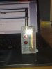
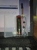
The result of my project was the uploaded picture

any way it works fine, but i have noticed that the vapor amount less than that produced by eGo or other mode using the same 18650 battery. also the life span of the fully charged battery has been increased for about two hours more. now i dont have a voltmeter to check out the volt in the mod, and am not a very good in electronics so i dont know whether the resistor causing the lack of power or anything else. Any ideas ??
 

Attachments

  • 27072011068.jpg
    27072011068.jpg
    21.4 KB · Views: 189
  • 27072011069.jpg
    27072011069.jpg
    21.5 KB · Views: 171
Last edited:

jrm850

Senior Member
ECF Veteran
Jun 18, 2011
159
21
Southeastern US
The resistor shouldn't make much difference other than how bright your LED is and a little change in battery life.

It appears that you have a cold solder joint between your ground wire and the atomizer connector that could be causing your low heat issue. You never want the solder looking frosty like that.

If you had a meter, I would check the resistance across your switch when closed. Switch quality is really important when you are dealing with loads as small as these heating coils.
 

squirrel64

Super Member
ECF Veteran
Verified Member
Oct 27, 2010
464
80
Va Skyline Drive Shenandoah River
. A volt meter might not show the problem. Unless you had one like this 510 Voltage Indicator.


Sometimes the voltage needs to be checked under load (with attie firing) in order to narrow the problem down. But more than likely you do have a cold solder loint. Which means the solder is sticking but it's not a good clean connection
 

jrm850

Senior Member
ECF Veteran
Jun 18, 2011
159
21
Southeastern US
A cold solder joint is where the solder doesn't completely "Wet" one of the surfaces. It is common when you are soldering two items of vastly different thermal capacitance. Your solder joint may be perfectly functional or may not. On the joint in question there is a ball of solder with a frosty apearance. the frosty appearance is usally caused my movement of the pieces before complete solidification. You want to be able to see the very edge of any joint taper to a flush edge on both parts and never want to see an edge curled under like you get with a ball. A tip to help in this situation is to touch the iron tip and solder to the larger piece until it starts to flow, then roll the tip to smaller component until the solder flows on on it. It can be tricky in some situations because the amount of het required to flow on the larger part might be enough to cook a component. In this case you would just melt a little more insulation on your wire. Everyone has their own techniques. I personally like a hotter iron than most becasue I feel like the quicker you get in and get out, the more localized the heat wil be.

An ohm meter would certainly be the place to start analyzing why your mod is cooler than you expect. This circuit has a 2-3ohm operational load. I just measured some cheap radio shack switches which averaged .5ohms across the poles right out of the package. These switches would decrease the power to the operational load by 17%-25% which is pretty significant in this application. Switches with copper contacts can have much higher resistance as the copper starts to oxidize.
 

Dudeman

Ultra Member
ECF Veteran
Verified Member
Dec 28, 2009
1,430
1,208
56
New Bedford, MA
Did you know...

With some very slight trimming, a MAP tank will fit inside one of those battery cases with an 18650. If you trim the access off the bottom of the atty connector and epoxy it to the bottom, it leaves just enough room to screw the MAP tank in there. All that sicks out is the drip tip. I made a sloppy version with less than acceptable epoxy and a tact switch thats been working good for a couple months now. It's nice to be able to hide an 18650 and MAP tank in the palm of your hand.
 
Status
Not open for further replies.

Users who are viewing this thread