I started vaping a couple months ago and up until about 2 weeks ago knew nothing about electronics. I'm a comp programmer so I can deal with logic, but electronics was just so much "black magic" as far as I have always been concerned. However, my new hobby (vaping) really piqued my interest in electronics - so I dived in, studying various modder posts and running electronic simulations to understand basic stuff like resistance, capacitance, voltage division, etc...
Here's the first "fruit" of my effort. It's a 5v mod with a MOSFET driven tactil switch stuffed into a 3xAAA box. The device has a master kill switch, tactile momentary, LED, and runs at 5V regulated. I could have used a regulator with a control pin or a variable volt regulator with an inhibit pin to support a low-amp switch, but I wanted to learn about MOSFETs and wanted some practice translating a schematic of my own to a component diagram for creating a circuit board.
This was a bunch of fun to build and I learned alot. Next project will be a variable output regulator using the inhibit pin (TI part) with a "normally closed" momentary - again, in a 3xAAA box. If anyone is interested I can post a complete tutorial on how the circuit was desigend and final version built including schematics and component placement diagrams. Like I said, 2-3 weeks ago I didn't even really understand what a resistor did in a circuit, now I can design mods - so really anyone can do it with some patience")
Here is my prototype (about 2" x 2" running off a lab power block I created last week)

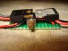
Here's the new circuit with my finger to show size - had to fit in part of one AAA battery slot in the box. I bent the MOSFET and the 5v regulator inward to reduce the length and also provide some support to the little tactile switch build onto the board.

Here's the installation

Final device

Here's the first "fruit" of my effort. It's a 5v mod with a MOSFET driven tactil switch stuffed into a 3xAAA box. The device has a master kill switch, tactile momentary, LED, and runs at 5V regulated. I could have used a regulator with a control pin or a variable volt regulator with an inhibit pin to support a low-amp switch, but I wanted to learn about MOSFETs and wanted some practice translating a schematic of my own to a component diagram for creating a circuit board.
This was a bunch of fun to build and I learned alot. Next project will be a variable output regulator using the inhibit pin (TI part) with a "normally closed" momentary - again, in a 3xAAA box. If anyone is interested I can post a complete tutorial on how the circuit was desigend and final version built including schematics and component placement diagrams. Like I said, 2-3 weeks ago I didn't even really understand what a resistor did in a circuit, now I can design mods - so really anyone can do it with some patience
Here is my prototype (about 2" x 2" running off a lab power block I created last week)
Here's the new circuit with my finger to show size - had to fit in part of one AAA battery slot in the box. I bent the MOSFET and the 5v regulator inward to reduce the length and also provide some support to the little tactile switch build onto the board.
Here's the installation
Final device