Here's my mod, and yes I MADE it, I didn't buy it. My part's list, instructions and pics are below. Please excuse the novel, but I'm not much one for vids.
Romisen CREE RC-A8: $15.99 (the black is $14.99) - Deal Extreme
TrustFire PCB 3.6V 880MaH 2pk: $4.49 - Deal Extreme
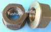
5/16" Push Nut - $1.39 - Home Depot Speciality nuts & bolts drawers.
1 Momentary switch - Normally Open - available at any Radioshack/Frys/Electronic's parts place. -- 4pk for $3.50
Tools Used:
Dremel/Roto Tool - cone-shaped grinding attachment (a fine round file will work too)
Drill with 5/16 drill bit
Hemostats or long-nose pliers
Soft-Face Hamer (amber) - $4.99 Harbor Freight
Soldering Iron
10MM Nut Driver
Tubing Cutter - $3.99 Harbor Freight
Voltmeter (With OHM Measurement) - $2.99 Harbor Freight
Bench Vise or some other way to grab and hold small parts.
Punch tool (Awl)
SO... for roughly $25 US dollars and just a little effort, you can have your own SD Clone . It takes me about an hour to toss one of these bad-girls together. The beauty is that EVERYTHING comes apart on this beautiful little torch.
Step 1 - Order your parts and wait. I suggest ordering more than one Flashlight and extra batteries, not because you're going to mess up - but because you're gonna LOVE the flashlight. It's better to order what you think you'll need in one shot, than have to wait for a SECOND order to come in.
Step 2 - Break down your RC-A8. Everything breaks down on this beauty.
1. Unscrew the Lens
2. Fit your long-nose pliars into the slots on either side of the led and unscrew.
3. Gently clip or unsolder the wire from the led, you'll use the wire later and if you're careful you'll only have this one solder-point.
4. Unscrew the lower part of the body. Insert Nut Driver in wide opening and gently tap-out the circuit board. Set Aside.
5. Remove Rubber cover from the switch, and unscrew switch assembly from the inside of the lower body with hemostats.
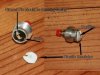
Step 3 - Replace the switch assembly.
1. You can do this any way you like, but I gently pry the insides out of the metal casing.
2. Use your dremel w/cone attachment to enlarge the hole so that the switch will fit completely through. It shouldn't require much enlarging.
3. Fold one prong on the switch flat and flush with the bottom of the switch, and again so that the "bottom" of the prong is pointing toward the button, then push it toward the body. You want this prong to firmly touch the metal casing after it's inserted.
4. Take the nut and washer off the switch.
5. Insert switch into the flashlight switch casing, screw on the nut an tighten with your 10mm Nut Driver. Check the OHMS between the casing and the prong that's still sticking up with the switch depressed. If it's not registering resistance, you may need to shim the other side of the switch to get a good connection.
6. Find something to insulate the remaining prong from the one that's folded over. I used a bit of heavy plastic I had lying about. Cut a circle the size of the switch. Cut a small slot in it to go around the remaining prong, and fold the prong inward over the plastic insulator. This prong will be touching the bottom of the battery. Make sure it sits above the edge of the metal casing. Personally, I grind down the casing (with a bench grinder) so that the bottom of the switch is above the rim.
7. Screw the casing back into the bottom 3rd of the flashlight.
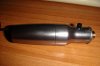
Step 4 - Prep the Middle 3rd.
1. Wrap some tape around the neck were you are going to cut, to keep from marring the the finish.
2. Use your tube cutter to cut it in half, slow and steady is the key.
3. Use your Roto with grinding tip to flatten the surface and then bevel slightly inward, this gives a nice clean edge.
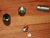
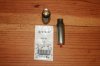
Step 5 - Make your adapter
1. You'll notice that the nut is almost a perfect fit.
2. Use your awl to tap an indention into the bottom of the nut, secure in vice and drill out with 5/16 drill bit.
3. Use Grind the top prongs down, this will enable you to "press fit" the battery adapter from your 401/901/801 whatever you like. The smaller adapters may not need any grinding at all, but the 901 does.
4. There are 2 ways to make the Push Nut - press fit the neck you just cut. First way is to use your awl and punch a few "outward facing" bumps. Second way is to put a few solder dabs around the middle of the Push Nut.
5. Press-fit your adapter into the "pronged" end of the Push Nut. The easy way is to screw the adapter onto a bad atomizer and use your soft-mallet to tap it into place. This protects both your fingers and the threads on the adapter.
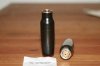
Step 6 - Put it all Together!
1. Thread the wire attached to the circut board through the neck and solder the wire to the center post of the adapter. (This is the reason for the big hole in the bottom) Clip the circuit board back into place, and press-fit the adapter into the neck of the flashlight.
2. Check OHMS between center post and threads on the INSIDE of the flashlight. There should be no shorts (needle doesn't move). Then touch the Outside of the adapter, and you should see resistance. If not, one of your press-fits doesn't have enough touch-points.
3. Insert Battery and screw together.
4. Check your voltage by touching center post and outside-threads of your battery adapter while depressing button. Mine registers 4.2v with a fully charged Trustfire.
5. Attach atomizer and ENJOY!
An advantage of using this Press Nut that the prongs make 4 additional vent holes. Very easy draw on these. If you want a stiffer draw, you can solder these closed.
Romisen CREE RC-A8: $15.99 (the black is $14.99) - Deal Extreme
TrustFire PCB 3.6V 880MaH 2pk: $4.49 - Deal Extreme
5/16" Push Nut - $1.39 - Home Depot Speciality nuts & bolts drawers.
1 Momentary switch - Normally Open - available at any Radioshack/Frys/Electronic's parts place. -- 4pk for $3.50
Tools Used:
Dremel/Roto Tool - cone-shaped grinding attachment (a fine round file will work too)
Drill with 5/16 drill bit
Hemostats or long-nose pliers
Soft-Face Hamer (amber) - $4.99 Harbor Freight
Soldering Iron
10MM Nut Driver
Tubing Cutter - $3.99 Harbor Freight
Voltmeter (With OHM Measurement) - $2.99 Harbor Freight
Bench Vise or some other way to grab and hold small parts.
Punch tool (Awl)
SO... for roughly $25 US dollars and just a little effort, you can have your own SD Clone
. It takes me about an hour to toss one of these bad-girls together. The beauty is that EVERYTHING comes apart on this beautiful little torch.Step 1 - Order your parts and wait. I suggest ordering more than one Flashlight and extra batteries, not because you're going to mess up - but because you're gonna LOVE the flashlight. It's better to order what you think you'll need in one shot, than have to wait for a SECOND order to come in.
Step 2 - Break down your RC-A8. Everything breaks down on this beauty.
1. Unscrew the Lens
2. Fit your long-nose pliars into the slots on either side of the led and unscrew.
3. Gently clip or unsolder the wire from the led, you'll use the wire later and if you're careful you'll only have this one solder-point.
4. Unscrew the lower part of the body. Insert Nut Driver in wide opening and gently tap-out the circuit board. Set Aside.
5. Remove Rubber cover from the switch, and unscrew switch assembly from the inside of the lower body with hemostats.
Step 3 - Replace the switch assembly.
1. You can do this any way you like, but I gently pry the insides out of the metal casing.
2. Use your dremel w/cone attachment to enlarge the hole so that the switch will fit completely through. It shouldn't require much enlarging.
3. Fold one prong on the switch flat and flush with the bottom of the switch, and again so that the "bottom" of the prong is pointing toward the button, then push it toward the body. You want this prong to firmly touch the metal casing after it's inserted.
4. Take the nut and washer off the switch.
5. Insert switch into the flashlight switch casing, screw on the nut an tighten with your 10mm Nut Driver. Check the OHMS between the casing and the prong that's still sticking up with the switch depressed. If it's not registering resistance, you may need to shim the other side of the switch to get a good connection.
6. Find something to insulate the remaining prong from the one that's folded over. I used a bit of heavy plastic I had lying about. Cut a circle the size of the switch. Cut a small slot in it to go around the remaining prong, and fold the prong inward over the plastic insulator. This prong will be touching the bottom of the battery. Make sure it sits above the edge of the metal casing. Personally, I grind down the casing (with a bench grinder) so that the bottom of the switch is above the rim.
7. Screw the casing back into the bottom 3rd of the flashlight.
Step 4 - Prep the Middle 3rd.
1. Wrap some tape around the neck were you are going to cut, to keep from marring the the finish.
2. Use your tube cutter to cut it in half, slow and steady is the key.
3. Use your Roto with grinding tip to flatten the surface and then bevel slightly inward, this gives a nice clean edge.
Step 5 - Make your adapter
1. You'll notice that the nut is almost a perfect fit.
2. Use your awl to tap an indention into the bottom of the nut, secure in vice and drill out with 5/16 drill bit.
3. Use Grind the top prongs down, this will enable you to "press fit" the battery adapter from your 401/901/801 whatever you like. The smaller adapters may not need any grinding at all, but the 901 does.
4. There are 2 ways to make the Push Nut - press fit the neck you just cut. First way is to use your awl and punch a few "outward facing" bumps. Second way is to put a few solder dabs around the middle of the Push Nut.
5. Press-fit your adapter into the "pronged" end of the Push Nut. The easy way is to screw the adapter onto a bad atomizer and use your soft-mallet to tap it into place. This protects both your fingers and the threads on the adapter.
Step 6 - Put it all Together!
1. Thread the wire attached to the circut board through the neck and solder the wire to the center post of the adapter. (This is the reason for the big hole in the bottom) Clip the circuit board back into place, and press-fit the adapter into the neck of the flashlight.
2. Check OHMS between center post and threads on the INSIDE of the flashlight. There should be no shorts (needle doesn't move). Then touch the Outside of the adapter, and you should see resistance. If not, one of your press-fits doesn't have enough touch-points.
3. Insert Battery and screw together.
4. Check your voltage by touching center post and outside-threads of your battery adapter while depressing button. Mine registers 4.2v with a fully charged Trustfire.
5. Attach atomizer and ENJOY!
An advantage of using this Press Nut that the prongs make 4 additional vent holes. Very easy draw on these. If you want a stiffer draw, you can solder these closed.
Attachments
Last edited:
")