
I've had an idea burning in my head for about 6 weeks now. Finally, I think I have it all down on paper except the wiring. The idea is to have a single 18650 battery power the VV unit (3.7V - 5.5v) and have it an Auto switch. I cannot find anything like this anywhere. Please let me know if I'm on the right track...
You are using an out of date browser. It may not display this or other websites correctly.
You should upgrade or use an alternative browser.
You should upgrade or use an alternative browser.
- Status
- Not open for further replies.
here is an auto switch..
510 Auto Switch
Here is a "booster circuit" with a normal push button switch
http://www.e-cigarette-forum.com/fo...44-44-mini-booster-box-mod-3.html#post3060934
Same booster circuit.......wiring diagram....
http://www.e-cigarette-forum.com/fo...44-44-mini-booster-box-mod-2.html#post2996366
Variable wattage DNA12 module
http://evolvapor.com/wp-content/uploads/dna12.pdf
Last edited:
I looked up the DE-SWADJ, and found two versions (1A and 3A max current) of a step-down voltage regulator. One amp is a bit low for an e-cig, so the 3A version would probably be more suitable.
Step-down converters require that the input voltage be higher than the output voltage, though, so you'd have to use two batteries in series to power the DE-SWADJ. The datasheet was also not very helpful compared to most that I've seen.
If you want a single battery solution, then you should go with a step-up (boost) regulator like those that retird pointed out. I've been looking at the TPS55340 recently, but have not tried it. It would require proper circuit design with several other components.
If you're looking for an assembled PCB solution, there is the DNA12 (or DNA20) and the Nivel Chip that are designed specifically for e-cigs, as well as generic regulator boards from places such as ebay, like ones mentioned in this thread:
http://www.e-cigarette-forum.com/forum/battery-mods/259577-just-lm2596-users.html
That one is a step-down, requiring two batteries, and not very efficient. It is pretty simple to use, and quite cheap to buy.
Also, the LEDs in your circuit would likely blow and/or drop your voltage to the coil. You need to limit the voltage and current through them, usually using a properly calculated resistor, and you do not want them in series with the atomizer. If you have a voltage display, they would likely not be necessary.
Speaking of the voltage display, I suspect that it would need to be connected to the high and low side of the regulator output, not just in series with the high side of the circuit.
I'd suggest reading through as many threads on VV builds in this forum as possible before tackling this.
Thank you fellas. I will be hitting the drawing board again in the morning...
Question: If Provari can do this with a single battery, how can I do it too?
Re-read the previous posts....you can do it with the dna12, dna20d, the nivel chip.....single battery booster chips.....
Here is an example mod...
Here is an example mod...
Attachments
Last edited:
hey everyone, I ordered one of those auto switches from madvapes, and it has 3 wires coming out of it...
2 questions if you dont mind
1.If i was planning on doing just a straight up 3.7v (no dna or nivel etc) what do I connect the 3 wires to?
and
2.can i solder a slightly thicker wire to those 3 wires that come presoldered onto the auto 510?
Thanks in advance,
L
2 questions if you dont mind
1.If i was planning on doing just a straight up 3.7v (no dna or nivel etc) what do I connect the 3 wires to?
and
2.can i solder a slightly thicker wire to those 3 wires that come presoldered onto the auto 510?
Thanks in advance,
L
From Madvapes:
510 Auto Switch
This is an automatic switch that can be used to make an auto box mod or device of your design that does not need a push button switch. We use these in our auto box mods and they work great.
The red wire is for power, the black wire is ground and the white wire is your control wire and activates the blue LED on the circuit board
From Madvapes:
510 Auto Switch
This is an automatic switch that can be used to make an auto box mod or device of your design that does not need a push button switch. We use these in our auto box mods and they work great.
The red wire is for power, the black wire is ground and the white wire is your control wire and activates the blue LED on the circuit board
Hi man...I'm really sorry, but I dont understand where to solder them to. Red to bat+ Black to bat- and white to LED/capacitor?
Sorry

L
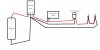
Guessing your switch looks like this...if not post a picture...

RED is positive lead to battery
Black is ground (negative lead to battery)
White shows it is already soldered to circuit board.
If you note the black wire has a bare spot (insulation removed) close to the circuit board for soldering...
Note.....keep juice from going in the unsealed auto switch....it can malfunction...
Last edited:
I don't believe a sealed 510 is going to work: the switch/actuator relies on the airflow thru the adaptor.
Right on ....just need to keep juice out of it....will edit...
I don't believe a sealed 510 is going to work: the switch/actuator relies on the airflow thru the adaptor.
Any chance you know where to pick up that same LED in red?
so I would need to break open the battery to get the LED out?
Thanks Retird!
Thanks Retird!
Thanks for that info...and btw, I really love your dna bb...
L
L
Ok time to revive this one. I promise I have smarter questions this time.
I really like the Evolv setup, can this be configured for an auto switch, or is it stuck for only firing buttons. I think I already know this one, but I need to ask.
EVOLV DNA20d
I really like the Evolv setup, can this be configured for an auto switch, or is it stuck for only firing buttons. I think I already know this one, but I need to ask.
EVOLV DNA20d
The DNA board only uses the switch for signal, so yes it would be a great fit with the DNA20.
- Status
- Not open for further replies.
Similar threads
- Replies
- 5
- Views
- 3K
- Replies
- 12
- Views
- 2K
- Replies
- 2
- Views
- 1K
Users who are viewing this thread
Total: 2 (members: 0, guests: 2)