I'm sure the answers to these questions are here somewhere but I just don't know where to start looking.
I've decided to build an OKR T10 box. I don't use reddit but was doing some searches there and found this.
http://www.reddit.com/r/cujo/comments/22jnpf/my_parts_list/
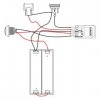
Now when I watched Goss's video of building a Duke he only uses the chip , a switch , 510 , battery sled and potentiometer.
My question is what is all the extra stuff for in that list. I found a wiring diagram for all those parts so I can build it easily enough but I'm just curious what they do and if they're truly needed.
I've ordered the OKR , pot, some magnets for the door , a few switches, a volt meter and a Fat Daddy 510. I think I'm going to use this for the box , it's a tad bigger than some of the popular ones but for my first build I want the extra space.
http://www.amazon.com/gp/aw/d/B005T...colid=3HPOCBTSFLQCA&coliid=IBFM42QQPY8G8&vs=1
Any help or links would be truly appreciated. Thanks.
I've decided to build an OKR T10 box. I don't use reddit but was doing some searches there and found this.
http://www.reddit.com/r/cujo/comments/22jnpf/my_parts_list/
Now when I watched Goss's video of building a Duke he only uses the chip , a switch , 510 , battery sled and potentiometer.
My question is what is all the extra stuff for in that list. I found a wiring diagram for all those parts so I can build it easily enough but I'm just curious what they do and if they're truly needed.
I've ordered the OKR , pot, some magnets for the door , a few switches, a volt meter and a Fat Daddy 510. I think I'm going to use this for the box , it's a tad bigger than some of the popular ones but for my first build I want the extra space.
http://www.amazon.com/gp/aw/d/B005T...colid=3HPOCBTSFLQCA&coliid=IBFM42QQPY8G8&vs=1
Any help or links would be truly appreciated. Thanks.