
I haven't got any questions atm but standby I am sure I'll come up with one sooner rather than later...
You are using an out of date browser. It may not display this or other websites correctly.
You should upgrade or use an alternative browser.
You should upgrade or use an alternative browser.
punchy187's insignificant stupid repetitive li-ion battery,pcb, and everything else thread...
- Thread starter punchy187
- Start date
- th_trl_thread_readers 0
- Status
- Not open for further replies.
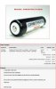
Better direction here with both the single thread and the choice of battery. Somehow there is still slight aftertaste of the Karate Kid plot happening, but I did notice the smaller font. The NCR18650A is indeed a much more reputable battery.
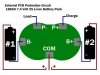
I got my PCB Circuit Protection Chips the other day so I can finally use the four Tenergy batteries to make two high voltage mods that I have been sitting on for more than a month. But they didn't come with instructions...go figure...and I found a diagram that gets me about 80% of the way but want to clarify a couple things before I start. I noticed the PCB that comes on protected batteries are clipped on not soldered how am I going to accomplish that I wonder? Also I uploaded a diagram of the chip I have and filled it using my best educated or uneducated guess. How close am I on the diagram and also need to clarify the charge and load terminal. Is the load the atomizer pin? What about the charge terminal?
Attachments

Last edited:
Your diagram is a bit off it should be battery 1 negitive to B-, battery 1 positive to COM, battery 2 negitive to COM, and battery 2 positive to B+. The P- is the negitive side of your load i.e atty and P+ is the positive side. The P- is also the negitive side of you power source to charge the batteries and P+ is the positive side.
OK. The way I have the diagram it is in parallel. P-would connect to the atomizer housing as the negative (or ground) and the P+ would connect to the atomizer pin as the positive. So the last thing is how do I make the connections? If I do a real quick drop solder making sure I don't heat the chip up at all except for the solder that drops would that work?
I just noticed something. The P- and P+ terminals are not medal like the other three. All it is is like a piece of aluminum foil. The likelihood of dropping solder on them and it sticking making a solid connection without something going wrong and screwing up the chip are at best 50/50. I have to be missing something here but don't know what it is.
it is not aluminum foil it is tinned copper. Those two are going to be easier to solder then the pads with built up metal. Those your going to have to heat up a bit before the solder will stick. You have to worry more about heating the batteries up then the PCB board. hopefully your using a battery holder or batteries with tabs. tabs are spot welded on so the cell doesn't heat up. soldering directly to a li ion will more then likely damage it.
Tin all your pads and wire ends before soldering together. Unless you have a really powerful iron i doubt your going to mess up the PCB. Watch the how to solder video that is a sticky here in the mod forum. It is a good video.
Tin all your pads and wire ends before soldering together. Unless you have a really powerful iron i doubt your going to mess up the PCB. Watch the how to solder video that is a sticky here in the mod forum. It is a good video.
I usually flux both ends that I am going to solder and tin the tip of the iron and unless something is dirty it usually solders pretty good that way for me anyway. I changed soldering irons from electric to butane using one of those BernzOmatic ones with the stand. They burn hella hot. Well I am going to give it a try now that I feel more confident about what to expect. Thanks.
One more thing is where does the switch fit in this configuration?
One more thing is where does the switch fit in this configuration?
Last edited:

take the switch out of there slap it on the atomizer pin line. although i guess it would work like , the B + and - technicly should go straight to the battery and the com straight to where the two batteries connect in series. With the switch on there the PCB will be able to detect the #1 battery voltage all the time but #2 battery it will only be able to detect it when the switch is pressed. Could cause issues.
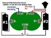
The surgery was successful. That was quite a bit easier than I thought it was going to be. I think these 18650 Tenergy 1400mAh batteries with a max discharge rate of 20C are way to strong for a high voltage mod. It burns to hot and ruins the flavor of the juice only holding the button down for 1 sec. To much current. They are perfect for a 3.7 volt mod. I am hoping the Orbtronic 3100mAh batteries I bought will be what I am looking for since their max discharge rate is 8.5C they might be perfect for my high voltage mod. Thanks for the help with the PCB configuration. This is how I ended up connecting everything in the diagram below. Now I have to make a container to enclose the mod in.
Attachments
Yeah you would have to use High Resistance Atomizers on that set up. Most folks slap a regulator on stacked cells like that, either 5 volts or a adjustable voltage regulator. Personally I like the adjustable because I prefer vaping @ around 4.5 volts
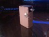
My latest mod. I ended up having something wrong with one of the Tenergy batteries I was using and got the Orbtronic batteries in the mail so I swapped the PCB and the Tenergy batteries out and put the Orbtronic batteries in. I made a battery holder built into the mod itself out of an old NiHM battery charger just using the connecters and built the map tank inside the mod also. I still need to put a cover around the drip tip and need to sand some more and then clear coat it.
Attachments


I have a stupid question. 2S1P means 2 batteries in series 1 in parallel I thought but every battery holder I look at planning to buy does not look like they are in series. Both negative and positive markings are on the same side so I don't know if the listings are marked wrong (which means everyone is marked wrong...unlikely...) or if I am confused again. Here is a picture of what I am talking about.
Attachments

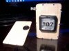
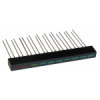
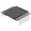
I bought these two items in the pictures. The 2 digit LCD screen does it need a micro controller to use it to read voltage? The other is a 10 LED light strip of sorts that has 6 green 2 yellow and 2 red LED lights on it. I was hoping to use it as a fuel guage for the voltage of the batteries in a mod. Is that possible? if so what would I need to do that?
Attachments
In most cases you can pull out the posts and reinstall them for series.I have a stupid question. 2S1P means 2 batteries in series 1 in parallel I thought but every battery holder I look at planning to buy does not look like they are in series. Both negative and positive markings are on the same side so I don't know if the listings are marked wrong (which means everyone is marked wrong...unlikely...) or if I am confused again. Here is a picture of what I am talking about.
Did not know you could do that. Good to know.
Yeah you would have to use High Resistance Atomizers on that set up. Most folks slap a regulator on stacked cells like that, either 5 volts or a adjustable voltage regulator. Personally I like the adjustable because I prefer vaping @ around 4.5 volts
Is this the type of regulator you are talking about? DC-DC Step Down Ajust PSU Module LM2756Hv Volt Regulator 5-6V to 1.25V-26V 20W | eBay
Better priceIs this the type of regulator you are talking about? DC-DC Step Down Ajust PSU Module LM2756Hv Volt Regulator 5-6V to 1.25V-26V 20W | eBay
LM2596 DC Step-Down Adjustable Converter Power Module | eBay
Many more here
http://www.e-cigarette-forum.com/forum/battery-mods/259577-just-lm2596-users.html
- Status
- Not open for further replies.
Similar threads
- Replies
- 2
- Views
- 676
- Replies
- 4
- Views
- 1K
- Replies
- 0
- Views
- 824
- Locked
- Replies
- 8
- Views
- 6K
Users who are viewing this thread
Total: 2 (members: 0, guests: 2)