
Is the irf630b suitable for use with tac switch?
You are using an out of date browser. It may not display this or other websites correctly.
You should upgrade or use an alternative browser.
You should upgrade or use an alternative browser.
quick mosfet question
- Thread starter DonG
- Start date
- th_trl_thread_readers 0
- Status
- Not open for further replies.
Should work if you use it with 2 3.7V batteries in series with step-down regulator. If you want to use it for 1 battery, better to use more suitable transistor, with less Rds and less Vgs
In any way this transistor is not the best for our purposes.
In any way this transistor is not the best for our purposes.
Or this one...cleaning up shop and hope to find one I can use without spending money.
APM3095P datasheet - P-channel Enhancement Mode Mosfet
APM3095P datasheet - P-channel Enhancement Mode Mosfet
Also have a couple of these:
http://doc.chipfind.ru/anpec/apm2023n.htm
http://doc.chipfind.ru/anpec/apm2023n.htm
Last edited:
Either one of those would work well with a single battery. One is a P channel and the other is a N channel so you can switch either polarity.Usually one works out better then other depending on the mods design.
Thanks Java.
starting to piece together my first wood mod.
Single 18650 with 04050 booster. Have a 47k pot I was thinking about adding to make it vv too.
A recommendation for the p or n and placement would be great. This will be my first use of a non mechanical switch.
starting to piece together my first wood mod.
Single 18650 with 04050 booster. Have a 47k pot I was thinking about adding to make it vv too.
A recommendation for the p or n and placement would be great. This will be my first use of a non mechanical switch.
Since your making a wood mod and it is non conductive you wont be using the case as a ground that pretty much opens you up to using either one. So it really depends on regulator and battery placement to which polarity would be easier to switch. If the regulator is placed closer to the positive of the battery you would have more room on the negative to add the mosfet and vice versa. So it really boils down to how you want to make.
Note using a mosfet is no excuse to use some POS, cheap tact.
Nuck for his Fistpack (the original VV TI 04050 mod) spent much time and energy finding a decent, reliable small switch to pair with a mosfet.
39-401 BLK Grayhill Inc | GH1349-ND | DigiKey
Nuck for his Fistpack (the original VV TI 04050 mod) spent much time and energy finding a decent, reliable small switch to pair with a mosfet.
39-401 BLK Grayhill Inc | GH1349-ND | DigiKey
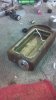
Thanks again guys. Looks like P it is. Fried my N bench testing before assembly. Rookie mistake assumed the center pin would be the gate/switch. Lol.
Then got the source and device leads reversed and damn thing would not completely turn off. Did not realize they were one way current flow like a diode.
Coming along nicely though.
Then got the source and device leads reversed and damn thing would not completely turn off. Did not realize they were one way current flow like a diode.
Coming along nicely though.
Attachments

Thanks again guys. Looks like P it is. Fried my N bench testing before assembly. Rookie mistake assumed the center pin would be the gate/switch. Lol.
Then got the source and device leads reversed and damn thing would not completely turn off. Did not realize they were one way current flow like a diode.
Coming along nicely though.
The gate will stay charged once it is activated. you need to add a resistor from gate to source this will pull it back down when your not pressing the switch. something around a 100k or higher should work well as long as your not doing a touch switch.
That's an odd choice. Usually 1- 10k does the trick nicely with N channels. Such a large value will slow the response time and extend the time it takes for it to ramp up to full saturation, which is where we want to be.The gate will stay charged once it is activated. you need to add a resistor from gate to source this will pull it back down when your not pressing the switch. something around a 100k or higher should work well as long as your not doing a touch switch.
That's an odd choice. Usually 1- 10k does the trick nicely with N channels. Such a large value will slow the response time and extend the time it takes for it to ramp up to full saturation, which is where we want to be.
It is the other way around. You want to use the highest resistance you can that can still fully desaturize the gate when the switch is off. It is much easier to overcome 100k resistance then it is 10k or 1 k going to the opposite polarity . so the higher the resistance of the resistor going to source the better and faster the gate saturation will be.
Could have sworn it worked without the resistor last night. Now getting a little over 2v through the mosfet without pressing the on button. Going to try the resistor and will post back.
Ok. Now switching properly. More help needed though. Getting 4.99 v output from the 04050board but output drops to 3.2 v with a 2.0ohm atty installed. Wtf?
Ok. Now switching properly. More help needed though. Getting 4.99 v output from the 04050board but output drops to 3.2 v with a 2.0ohm atty installed. Wtf?
What are you using to power it. Boost circuits require some pretty stout batteries. Also did you install caps for it.
My ptn04050c module doesn't drop but a few 100ths of a volt powered by a Panasonic 18650
What are you using to power it. Boost circuits require some pretty stout batteries. Also did you install caps for it.
My ptn04050c module doesn't drop but a few 100ths of a volt powered by a Panasonic 18650
Sony 18650 battery. 100uf caps. Maybe time to try the imr batteries? Definitely better vapor than the same battery without the booster but get tde feeling something just isnt right with it. Almost as if amperage is being boosted instead of voltage.
That Sony should boost it just fine. Data sheet says something about the control pin needs a dedicated line straight to the ground pin for regulator stability. Not sure if that has anything to do with it , about all i got off the top of my head. Are the caps electrolytic ?
That Sony should boost it just fine. Data sheet says something about the control pin needs a dedicated line straight to the ground pin for regulator stability. Not sure if that has anything to do with it , about all i got off the top of my head. Are the caps electrolytic ?
P mos. Direct to ground with switch only interruption. Caps are cylindrical. Not really sure if they are electrolytic. Could weak battery uch connection be a problem? To me the contacts seem as though they might be questionable even thpugh working. None of the typical underpowerex whone from the booster.
I few tidbits I gathered over time.It is the other way around. You want to use the highest resistance you can that can still fully desaturize the gate when the switch is off. It is much easier to overcome 100k resistance then it is 10k or 1 k going to the opposite polarity . so the higher the resistance of the resistor going to source the better and faster the gate saturation will be.
Mosfets have 3 regions of operation that we will concern ourselves:
The first is cut-off mode, when the mosfet does not conduct.
The second is the saturation mode, when the mosfet is switched on and is conducting with a very low drain to source resistance.
The third region is in between cut-off and saturation, and is known as the triode region. This is the region where the mosfet begins to conduct, but has a high channel resistance.
Gate capacitance in mosfets is also an issue. A higher gate capacitance will increase the time it takes for the mosfet to switch on and off. Ideally, you want to have the mosfet switching on and off as quickly as possible, in order to spend as little time as possible in the triode region. Slow switching will result in much higher channel resistances, which in turn will result in more power dissipation across the mosfet, causing the circuit to become less efficient, and the mosfets to heat up.
Also, you must make sure the gates of your mosfets see as little resistance as possible. For example, a high resistance to ground will cause the gate capacitance of an N-Mos to discharge much slower than if the resistance was low. This results in the mosfet spending more time in the triode region.
I few tidbits I gathered over time.
I half way agree with you there. Too much resistance will slow down the de-saturation of the gate but it makes saturation quicker. Don't take my word for it, Do a real world test slap a mosfet with a switch on the gate to a breadboard wire you up some power . Slap a 100ohm resistor from gate to source. now hit the switch the mosfet wont turn on. as you add resistance you will get to a point where it does turn on but it will be slow and lagging and not fully saturate. Once you get enough resistance added it will fully saturate. Now if we go to the other extreme and add a 100 Mohm resistor and hit the switch it will turn on with a quickness and fully saturate but once you let off the switch it will stay on. Now as we go down with resistance we will get to a point where the mosfet will turn off but it will be slow and laggy. keep going down and it will fully de-saturate. the reason i like a higher value resistor is i can care less if it is a bit laggy shutting off but i can't stand having it lag when i hit the switch. When i hit the switch i want full power going to the atomizer not waiting a sec or two for it to ramp up.
Last edited:
- Status
- Not open for further replies.
Similar threads
- Replies
- 22
- Views
- 8K
- Replies
- 10
- Views
- 2K
- Replies
- 10
- Views
- 10K
- Replies
- 9
- Views
- 1K
Users who are viewing this thread
Total: 2 (members: 0, guests: 2)