mosfet wiring question

Status
Not open for further replies.

windxrunner

Super Member
ECF Veteran
Verified Member
Aug 23, 2014
438
219
Portland, OR
Well, I have decided to use a mosfet. I have to make a decision on how to wire it, though.

Here's the two I'm considering.

The first has the positive going from the mosfet, to the switch(es), to the batteries, then to the atty. Like this:
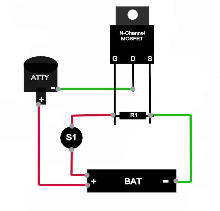
GZWv6hw.jpg


The second has the positive going from the batteries to the switches, then that positive wire joins the mosfet wire coming from the gate before they both become one and go to the atty. Like this:
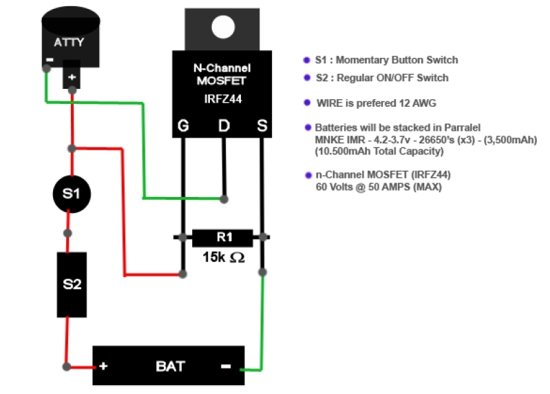
8UvgixV.jpg


The second one is safer, is my first impression. what do you guys think?
 

DaveP

PV Master & Musician
ECF Veteran
May 22, 2010
16,733
42,641
Central GA
Option 1 would be my choice since it uses one battery. It needs an on-off switch.

As for option 2, I wouldn't knowingly stand close to anyone vaping with stacked batteries unless the circuit had protection against reverse charging. All it takes is one battery at low potential and the other fully charged and the higher charged battery will try to equalize the voltages by draining potential into the lowly charged battery. They heat up very quickly when that happens. All the news stories about mods that blew up used stacked batteries. 26650's can be scary when that happens and choice 2 says that there are three 26650's in parallel. That's a small welder!

You might want to look at DNA30 vape mods for some protection or engineer a high amp diode into the battery circuit for option 2 that would prevent reverse current flow by only allowing voltage to flow in one direction. Some DNA30's use two batteries and it's a tried and true design with over-current protection.
 
Last edited:

AzPlumber

Vaping Master
ECF Veteran
Verified Member
Aug 28, 2011
5,051
9,789
Arizona
I know everyone thinks parallel is safer than series but I would still fuse each battery. If not fused and one battery fails the other will take the full load. If your counting on the batteries to split the current load this will go bad quickly. On top of that the good battery will be pushing current into the failed battery.
 

Dampmaskin

Ultra Member
ECF Veteran
Verified Member
Jan 28, 2014
1,042
1,157
Norway
www.steam-engine.org
The master switch on pos. side before any other connections.

Agreed, the master switch should be connected directly to the battery +.

Remember to use a relatively high current master switch, although arcing shouldn't be a problem as long as you don't operate the master switch while the MOSFET is open.

ETA:

I'm thinking something like this ought to work:
mosfetsetup.jpg

And be aware of grounding. If you're building in a metal box, the 510 will probably be grounded via the chassis. In that case, also grounding the MOSFET to the chassis would be a bad idea (at least with the diagram in this post).
 
Last edited:

windxrunner

Super Member
ECF Veteran
Verified Member
Aug 23, 2014
438
219
Portland, OR
gotcha. so you're suggesting I don't ground the mosfet to the negative side of the battery, but letting the 510 touch metal is cool. right? why is that? all the diagrams I've seen have the drain going to the ground on the 510 and the source going to the negative side of the battery, why is your diagram different? i just really want to understand this and I want to wire this box the best way possible.

i plan on using a 10-16 amp switch. while that is the AC rating, that should be high enough, especially when wired correctly, yes?
 
Last edited:

somun

Full Member
Jul 24, 2014
21
9
Santa Clara, CA, USA
Agreed, the master switch should be connected directly to the battery +.

Remember to use a relatively high current master switch, although arcing shouldn't be a problem as long as you don't operate the master switch while the MOSFET is open.

ETA:

I'm thinking something like this ought to work:
View attachment 374773

And be aware of grounding. If you're building in a metal box, the 510 will probably be grounded via the chassis. In that case, also grounding the MOSFET to the chassis would be a bad idea (at least with the diagram in this post).

I don't think that diagram is correct. It would not work properly. N Mosfet should be used as a low side switch.

Besides it defeats the purpose to introduce yet another high current switch in the mix.
 

somun

Full Member
Jul 24, 2014
21
9
Santa Clara, CA, USA
Yes you can technically connect the batteries that way but please be aware that the mosfet does not protect you from putting the batteries in reverse order which would create a direct short between them, quite possibly causing catastrophic failure. I would suggest that you consider using fuses. I believe there's a sticky thread right here about fuses.
 
Status
Not open for further replies.

Users who are viewing this thread