So I found this...

Status
Not open for further replies.

nicotime

Ultra Member
ECF Veteran
Nov 22, 2009
1,951
862
Montoursville, PA
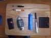
So I got this phone charger in a discount bin for $6 and I want to see if I can make a mod out of it to use while I'm building my own JB. It has two blue LED's on each side that flash when charging. It puts out around 5-6 volts...meter fluctuates when trying to get a reading?? How it makes 6 volts with two 1.5 volt batteries I dont know... a transformer of some kind on the board?? What I would like to do is make an adapter out of the jack (like warp1900's) to plug in any atomizer in it. I think I can get a button mounted in the center of the body between the batts and by the board, but I dont know if I can make the board function the way I want. I would like to keep the LED's and either run two 14500's (would need another protection circuit?) or have it to where I could switch to either batt when one dies...like a spare fuel tank. Can one of you electronic guru's look at the circuit board and give me my options or tell me I am dreaming? Speak slow because electronics I be dumb. :confused:

P60.jpg

P64.jpg

P65.jpg

P66.jpg

P67.jpg

P69.jpg

P70.jpg

P71.jpg

P72.jpg

P73.jpg
 

Jason365

Super Member
ECF Veteran
Aug 18, 2009
388
0
ATX
I have one of those, I never checked the voltage with batteries in it though.

It was my assumption the the output would too low to power an atty.

It is a charger and those usually have about 500 ma output to slow charge a device.

You need at least 1500 ma to have it work as an ecig mod.

This is all speculative as I don't know for sure. Its just what I have learned from the inter webs..

Jason
 

nicotime

Ultra Member
ECF Veteran
Nov 22, 2009
1,951
862
Montoursville, PA
WOW, that thing would be GREAT, hope it works out. we sell them at RadioShack. ima have to look into this. good size too. that litle rubber looking piece on he bottom would be a great button

Thats the first thing I thought too...it has one on both sides that you squeeze to take that end piece off to change the batts. Could be converted though but I want to leave that as is.

I have one of those, I never checked the voltage with batteries in it though.

It was my assumption the the output would too low to power an atty.

It is a charger and those usually have about 500 ma output to slow charge a device.

You need at least 1500 ma to have it work as an ecig mod.

This is all speculative as I don't know for sure. Its just what I have learned from the inter webs..

Jason

Your right Jason, I know that I cant run it as is so I have to bypass the board for direct batt power to the jack, but I want to save the LED's and have them flash when the atty is powered up and MAYBE flash when batt power cuts off like an e-cig batt...but thats not real important to me. I can tell by now when the batt is almost done when vaping before it flashes anyway.
I did find this about the IC chip on it..so this answers my ?? on how 2- 1.5v batts make 6v.
http://www.techtium.com/PDF/TEC103-shortview.pdf

Wish I knew what the other stuff is on the board...besides the LED's... instead of sitting here Googleing #'s on chips. :confused:

Thanks guys!
 

henrid84

Super Member
ECF Veteran
Dec 3, 2009
482
0
40
houston
Ok...does anyone at least see a point where I can tap in to use the LED's? I would probe the board but I know they at least need a resistor in the circuit and I dont want to burn them out.

i can see solder blotches on either side of the LED, or is that my eyes playing tricks. you say your gonna wanna bypass the board anyway? if so, dont even worry about the LED's get some new ones custom colored to your liking, about $2, keeping the entire board just to keep the LED's is sacrificing some much needed real estate. if you do want to keep them, just solder on a couple resistors and bypass the rest of the board.
 

nicotime

Ultra Member
ECF Veteran
Nov 22, 2009
1,951
862
Montoursville, PA
i can see solder blotches on either side of the LED, or is that my eyes playing tricks. you say your gonna wanna bypass the board anyway? if so, dont even worry about the LED's get some new ones custom colored to your liking, about $2, keeping the entire board just to keep the LED's is sacrificing some much needed real estate. if you do want to keep them, just solder on a couple resistors and bypass the rest of the board.

There is a tiny rectangle component beside it but I dont know if it is a resistor or what...I know I would have to tap in with a resistor in the circuit. I could replace them but they line up with a clear plastic lens of sort that wraps around the front which acts like a fiber optic effect to transfer the light, but yes I could duplicate the position of the LED's. I still need the board to hold the jack in place anyway, thats why I want to try to keep them...would be much neater and compact. As far as bypassing the board...I would just bypass the circuitry to the jack to get full voltage from the batts because the board doesnt put out the mA's needed. I may just end up mounting a 510 connector to it instead of the jack. Do you know what the rectangle components are? They are the black (and grey) ones with silver solder contact on each side.

Thanks henrid.
 

nicotime

Ultra Member
ECF Veteran
Nov 22, 2009
1,951
862
Montoursville, PA
Yes the two wires from the diodes join along with the LED wire. I thought a resistor is needed for a LED to reduce the voltage. I was thinking diodes because if one batt had a different level of charge the other one would in charge the lower one to balance. I didn't know if that would cause any problems or blow the batt. So your saying I can delete the diodes and still be safe and have protected batts?
 

nicotime

Ultra Member
ECF Veteran
Nov 22, 2009
1,951
862
Montoursville, PA
Your probably right Henrid...hard to isolate that circuit anyway so I might have to scrape the board and add a led and use the one side for the button.

So would connecting 2 14500's in parallel be a problem with the protection circuit or cause an explosion when the two batts try to equal out their voltage differences? Also, if it would work...would 2- 900mAh's then be like 1 1800mAh?
 

nicotime

Ultra Member
ECF Veteran
Nov 22, 2009
1,951
862
Montoursville, PA
Yeah I tried them first and they are tight. I see what you mean vendo, not much surface area. Not a lot of room in this thing for sure. I'm going to cut the springs back and open some places with my flex shaft tool. I got the atty end done now I just have to shoehorn a switch in the batt end...should be an adventure.
 
Status
Not open for further replies.

Users who are viewing this thread