
I bought a set of six from Grizzly off of Amazon for about $25. 1/8" through 1/2" with four flutes. Comes with a nice wooden block holder.
You are using an out of date browser. It may not display this or other websites correctly.
You should upgrade or use an alternative browser.
You should upgrade or use an alternative browser.
Mike n Tibs DNA Mods!
- Thread starter Proetus
- Start date
- th_trl_thread_readers 0
- Status
- Not open for further replies.
I made some major progress today despite too many other things to do. Got the buttons milled down, added clamps to the top rail to make sure the board sled doesn't move in any direction, found out I don't have enough room for the balance connector, converted the balance connector into a wired connector.
I still need to file flats on the buttons and add cleats to keep them from rotating. I also need to add two cleats to at as a battery retainer, I'm using magnets on the case and want to be absolutely sure it can't fall out accidentally.
Completed rail supports for the board sled -

Another view of the rail system -

A test assembly to make sure it all fits -

I doubt you could print the boxes alone for under $100, but I could be wrong.Hotcig stole my idea that I stole from Innokin. I was thinking 3D printed boxes, smaller for the chip and 510 and various sizes for different batteries

Anyone see if they're offering additional batteries, and what kind of price, for that thing?
Anyone see if they're offering additional batteries, and what kind of price, for that thing?
i believe october was the release date given for spare batteries
")
I seriously wish I could draw in cad and design 3d files. I think that would be so cool.Hotcig stole my idea that I stole from Innokin. I was thinking 3D printed boxes, smaller for the chip and 510 and various sizes for different batteries
I seriously wish I could draw in cad and design 3d files. I think that would be so cool.
Download sketchup....dedicate four weeks of two hours a day.
$149.00 HOTCIG D-N-A 200W 900mAh TC Temperature Control VW Variable Wattage AVP Box Mod - 1-200W / 200-600'F / aluminum / US plug balance charger at FastTech - Worldwide Free Shipping
Coupon Code MAP for 124.00 preorder
Coupon Code MAP for 124.00 preorder
Anyone see if they're offering additional batteries, and what kind of price, for that thing?


Hey that's pretty cool looking!
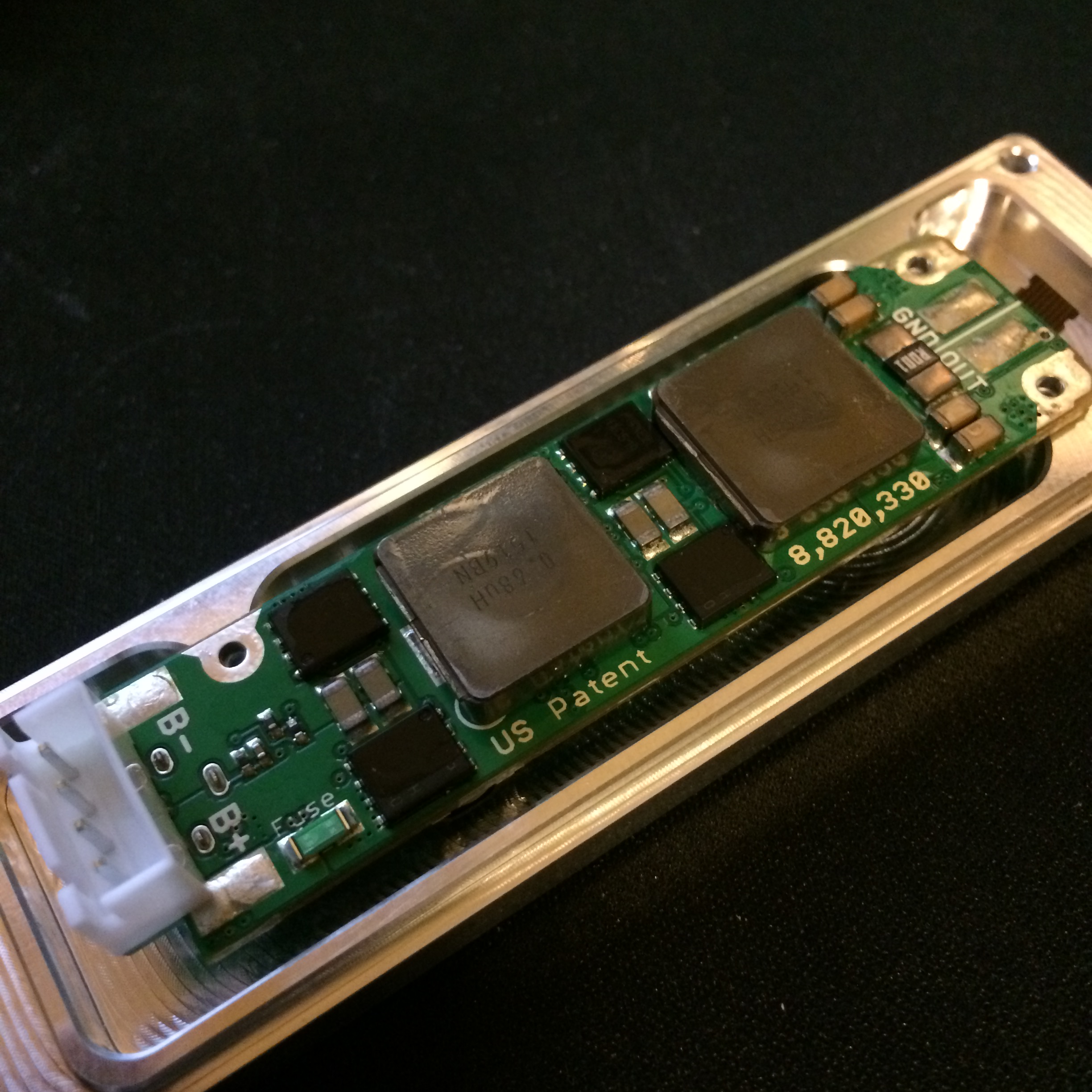
Nice. I too have a strain relief loop for the 510. Yours seems really long. I was curious if mine was making an impact on performance.
Thanks BRD! I tried to make the connections shorter originally, but my 510 is basically sitting right on top of the atty out pads, so i needed more length. I'm sure the v drop through this massive 12 gauge is minimal.Nice. I too have a strain relief loop for the 510. Yours seems really long. I was curious if mine was making an impact on performance.
I have decided to build a Triple Li-Ion DNA. Or at least, try to build
Unfortunately, it has become obvious that I couldn't use any stock battery connector due to space limitation (that I have set )
)
So, I need to make or get made the connectors myself.
The only question is the material and I could use some expert advise here.
ATM I have 3 (2.5 options) and some thoughts:
So, what do you think?
Unfortunately, it has become obvious that I couldn't use any stock battery connector due to space limitation (that I have set
)So, I need to make or get made the connectors myself.
The only question is the material and I could use some expert advise here.
ATM I have 3 (2.5 options) and some thoughts:
- Pure copper rod for the connectors and 5 x 0.75mm flat wire for the bars).
+ low resistivity
+the quantity of materials I need to buy would leave room for some trial and error
- material cost
-corrosion???
-aesthetic of the end result (well, I got limitations both skills and tool wise)
+the quantity of materials I need to buy would leave room for some trial and error
- material cost
-corrosion???
-aesthetic of the end result (well, I got limitations both skills and tool wise)
- 3D printed Brass (15% zinc, 5% tin, and 80% copper)
+aesthetic
+easy to make
~ probably cheaper than copper but still pricey
-relatively higher resistance (though, I can design quite thick bars and connectors if needed)
-???? I no nothing about brass
+easy to make
~ probably cheaper than copper but still pricey
-relatively higher resistance (though, I can design quite thick bars and connectors if needed)
-???? I no nothing about brass
- Economy connectors made of stainless steel Li-Ion Battery replacement caps and wire
+ price
-resistance
-expected aesthetic
-space (an up/down moving 14ga wire +insulation needs more room than a 1 mm bar that I would leave uninsulated for the mod will be 3D printed.
-resistance
-expected aesthetic
-space (an up/down moving 14ga wire +insulation needs more room than a 1 mm bar that I would leave uninsulated for the mod will be 3D printed.
So, what do you think?
Could you clarify what you mean by the connector? I haven't finished my first up of coffee, yet. Do you mean a connector to allow battery removal with the batteries as a unit, or assembly, or separate connectors for the batteries themselves? Maybe a sketch of the mod design would help.
3d printed brass as in the shapeways product using 3d printed was and then a casting?
Sorry, my bad.Could you clarify what you mean by the connector? I haven't finished my first up of coffee, yet. Do you mean a connector to allow battery removal with the batteries as a unit, or assembly, or separate connectors for the batteries themselves? Maybe a sketch of the mod design would help.
I need custom battery contacts for Li-Ion, not connectors. I want to remove the batteries individually.
The geometry is pretty simple:
At least on paper
Single contact w/ solder bar on the left, dual - to + on the right
yes, that is the one I am thinking about3d printed brass as in the shapeways product using 3d printed was and then a casting?
I'd make the contacts from brass or copper rods or bolts, machined with a file in a drill press to get the right size and shape. Get the diameter correct, then shape the contact end and the cut them to approximate length. File to get the length exact.
For the bars, again, either brass or copper bar stock. Any machining for the rods can be done with a Dremel and a file, assuming you have a vice or other clamping method.
Solder them together and install.
Brass or copper will have better conductivity that stainless, plus both are a lot easier to work than stainless.
My experience with a stainless printed part from Shapeways was not very good. Tolerances go way out when it goes from the plastic model to the mold for casting.
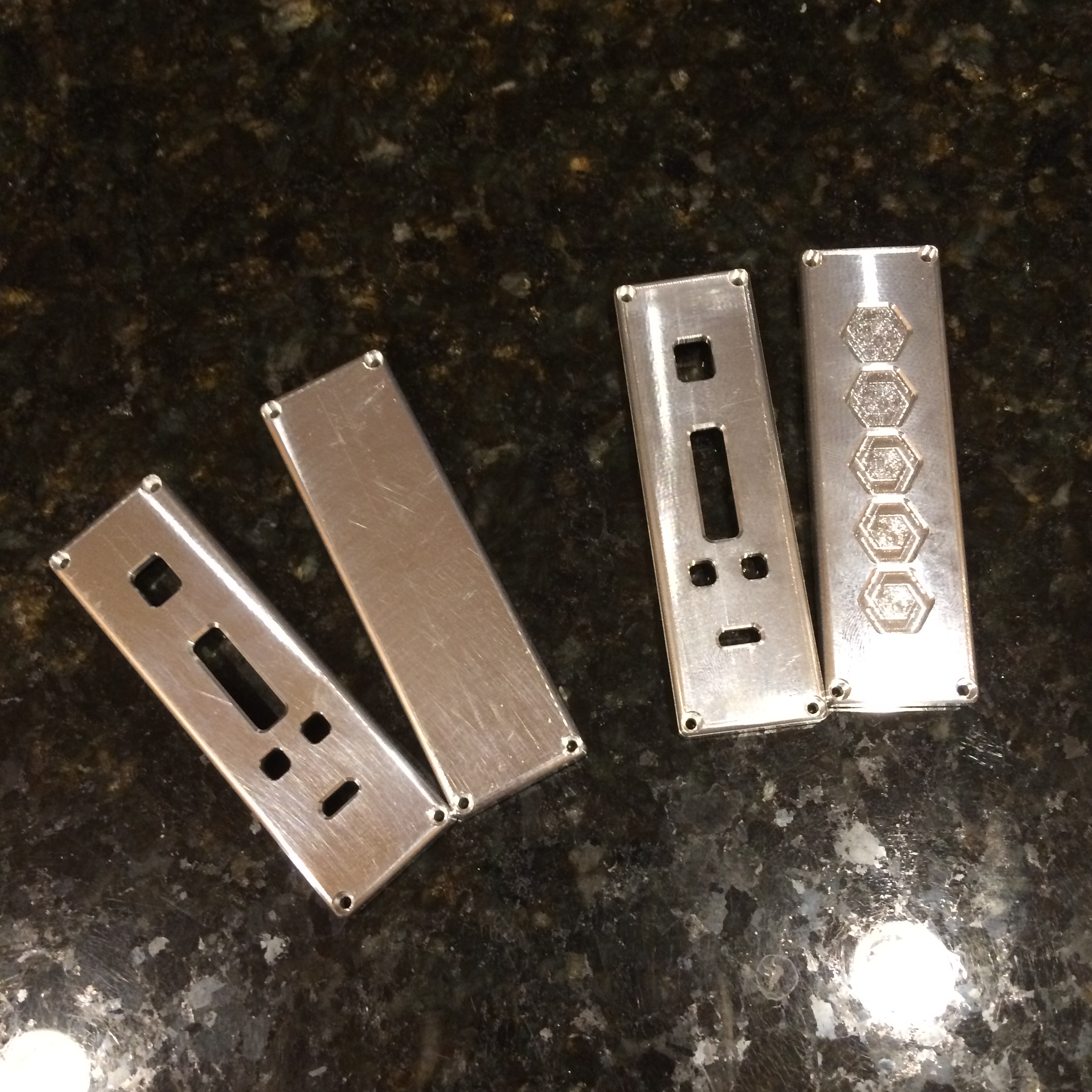
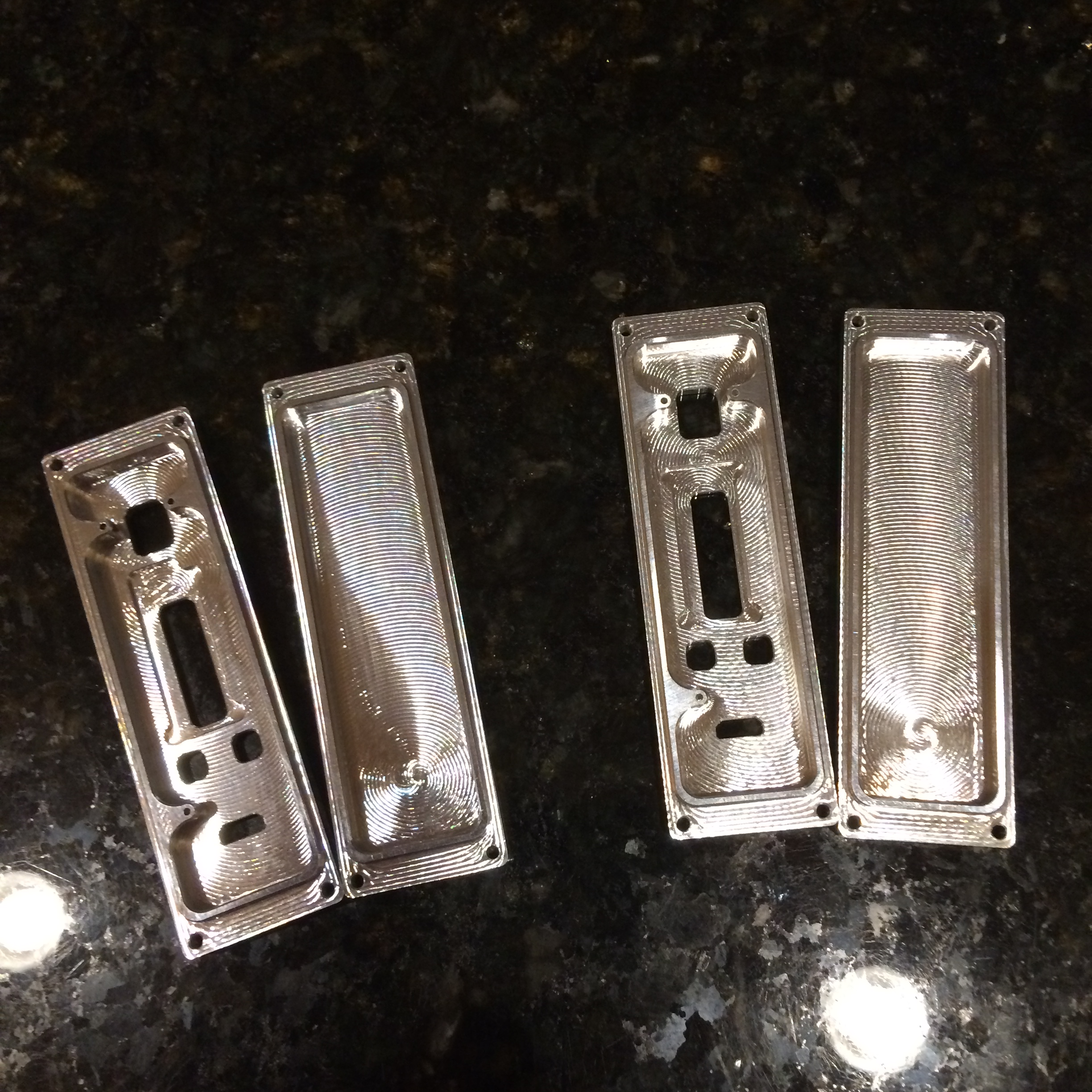
Made a second set of covers for my DNA200 mod. First set is on the right, latest set is on the left. Had to make a few changes to the inside of the front cover to give a little more cable relief for the screen. Now onto the main body and buttons! I'm really, really hoping to get at least one complete device done with this long holiday weekend.

- Status
- Not open for further replies.
Similar threads
- Replies
- 2
- Views
- 876
- Replies
- 6
- Views
- 822
- Replies
- 24
- Views
- 2K
- Replies
- 0
- Views
- 215
Users who are viewing this thread
Total: 3 (members: 0, guests: 3)