Can anybody explain to me exactly how mechanicals work? (the little details)

Status
Not open for further replies.

treehead

Ultra Member
ECF Veteran
Feb 18, 2014
1,477
1,311
Anchorage, AK, USA
f4nydxR.jpg


Hey guys! This may be a very vague question, but there's only a few things about the flow of power through a mechanical mod that I'm foggy on.

-I know positive connection is actually where the power connects to the topper.

-That the whole body of the mechanical is actually part of the circuit? (right?)

-That when you fire the button, that allows the current to start actually flowing to the topper? (So is the act of contacting with the negative side of battery, actually grounding the battery? This is the part I'm most fuzzy about, does the negative current run up through the mechanical mod body, and meet with the positive pin? Any explanation of the moment of firing action, would be oh-so-appreciated.)

-The part I understand almost completely is the physics of metals & conductivity, silver & copper are the best, magnets eliminate the volt drop of springs, a larger surface area between the connections and the battery is better, less threading is better (seemless tubes).

***This is just to give you an idea that I have a basic understanding of electricity, and "physics" lol, I don't necessarily need everything spelled out. The one thing I'm having trouble grasping is how the mechanic mod's body is actually part of the circuit, that actual connection of positive to negative with the firing buttond. My brain is telling me that when you fire, the negative side has to go through the metal of the tubing and caps, and then join with the actual positive side of the battery to start flowing, is this right? So would this mean the more conductive metal you have would be a good thing? Or would a thicker tube just "get in the way". I want to say more metal is better for volt drop, (as long as it's above 50% would be a good thing, because it would be more to conduct, and if it's less like stainless or brass even, then the less metal would be good, because it less to "get in the way" of conduction.) but I could be wrong.

I probably am wrong :p, just seeing if any of you smarties on ECF knew already, as I furiously scour the internet researching. Thank you SOOOOOOOO much in advance, I'm thinking about making my own mechanical mod soon, maybe even just the tube itself if it's too tricky at first. Any information on where to buy mechanical mod connection pins/screws would be awesome as well.

Thank ya so so so much if you have any input whatsoever, I'm tired of giving an arm and a leg for a mechanical that I really want, so I bought a nicely priced metal lathe off of craigslist, and plan to start making my own vapequipment! :D

Vape on!:vapor:

VKttVlu.png
 

VaPreis

Ultra Member
ECF Veteran
Verified Member
Oct 5, 2013
2,043
2,273
St. Louis, MO
The center pin of the 510 connection is your positive connection to the battery and is always in contact with the battery.

The threaded section of the 510 is your negative connection and is always in contact with the metal body of the mod.

The negative terminal of the battery is isolated from the body of the mod, usually by an insulator in the switch. Pressing the switch to make contact with the negative side of the battery closes the circuit between the battery and the body of the mod.

Current flows. Vape occurs. Enjoyment ensues. :)
 

WattWick

Vaping Master
ECF Veteran
Feb 16, 2013
3,593
5,429
Cold Norway
This is the part I'm most fuzzy about, does the negative current run up through the mechanical mod body, and meet with the positive pin? Any explanation of the moment of firing action, would be oh-so-appreciated.)

Negative current does not meet with the positive pin. There is an insulator between the mod body and the positive pin to keep them separate. Else you'd have a short. The contact point between negative and positive is your atty coil. Since the coil has resistance, this is not a dead short. And since it's resistive, it heats up :)
 

treehead

Ultra Member
ECF Veteran
Feb 18, 2014
1,477
1,311
Anchorage, AK, USA
The center pin of the 510 connection is your positive connection to the battery and is always in contact with the battery.

The threaded section of the 510 is your negative connection and is always in contact with the metal body of the mod.

The negative terminal of the battery is isolated from the body of the mod, usually by an insulator in the switch. Pressing the switch to make contact with the negative side of the battery closes the circuit between the battery and the body of the mod.


Current flows. Vape occurs. Enjoyment ensues. :)

Thanks brother, more than you know. What was throwing me off, is that I was always taught that positive flows to negative. Whereas in real-world physics (I just read online lol :p), the electrons (-) actually want to flow towards the + to fill the electron "gaps". I was always taught the opposite! What the hell is wrong with schools nowadays XD! It really cleared it up for me when you reminded me that the threading is where the negative really comes into contact with the positive. (I knew that duh! :facepalm: That's why you attach the negative end of your multimeter to the threading, stupid brain! Sometimes the obvious is the hardest to see in my case :lol)
~Once I found out that I'd been taught the opposite (which was causing the brain fart), and that you verified negative connects with the threading, now I have a clear image of how the current flows. Thanks sooo much man, you made my day, now I can start designing a "revolutionary" mechanical :p, just kidding I'm not that smart. I had the idea instead of using the body of the mechanical as the negative conductor, why not use a direct silver wire/cable, or at least a more direct method (like making a mini negative "shell" around the battery, that goes from the negative side of the battery directly around it in a smaller tube (insulated from the actual body) and then tapers off to join with the threads once the whole shell is pushed upwards.

~ That way the body can be whatever material you think looks cool, the actual negative conductor can be a smaller "cocoon" around the battery (so you can use something more expensive like silver (115% conductivity) and use less of it, plus since it's soft it'll be on the inside of your mod, thus not able to be crushed. I think I've got a decent, or at least unique idea going.

Again much appreciated brother. :D
 

treehead

Ultra Member
ECF Veteran
Feb 18, 2014
1,477
1,311
Anchorage, AK, USA
Negative current does not meet with the positive pin. There is an insulator between the mod body and the positive pin to keep them separate. Else you'd have a short. The contact point between negative and positive is your atty coil. Since the coil has resistance, this is not a dead short. And since it's resistive, it heats up :)

Thanks for the input man, I just had a crash course in circuit physics on the siemens site lol, I totally forgot they were insulated from eachother, it wouldn't be anything but a handwarmer if they weren't! XD This was one of the reasons for the brain-fart too, I pretty much had it backwards, and wasn't getting that the coil itself is the resistor lol.

~I'm already thinking about building a parallel dual 18650 tube, but maybe I'll try a single for my first one. A box is coming soon though, I have some carbon fiber left over from some homemade car parts, that'll make a spiffy box, and I didn't know they had battery hardware for DIY box-mods :). My mind is just exploding now, thanks guys.
 

treehead

Ultra Member
ECF Veteran
Feb 18, 2014
1,477
1,311
Anchorage, AK, USA
Anybody that happens to check on this, here's an update. I'm going for a totally pure silver circuit (115% conductivity) for everything but the battery and the negative 510 threads (because unfortunately I couldn't find any, or copper, oh well still should have a mean volt drop). Instead of using the body of the mechanical mod as the negative circuit, I'll actually be using a 99.999% silver 14 gauge (maybe 2 on opposite sides) wire to connect the negative terminal to the 510 threads (insulated with heat-shrink, this way the thick silver wire(s) are the actual circuit instead of the body which can be anything now.). I have solid silver contacts from a Chi-you replacement upgrade kit (my favorite adjustable positive contact style, nice wide contacts). Some pure silver solder if needed, as well as a square 2ft slab of black delrin and some washers for insulation.

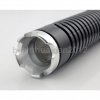
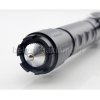
And to house my circuitry and button setup, I found a cool looking tactical flashlight, that's designed for heat dissapation, and has a perfect form for this project!
flashlight.jpgfl.JPG
 

Top_Bunk

Full Member
Verified Member
Nov 3, 2013
40
29
Cbus!
I like your ambition, but there are a few flaws in the plan.

Silver wire has a resistance of 1.59x10^-8/m, which is only slightly better than copper (1.68x10^-8/m). Now take into consideration that resistance increases as wire gauge get smaller. The body of the mod is essentially a really really thick gauge wire, and you'll be replacing it with a tiny 14g silver wire. You're likely to end up with a higher resistance than if you would just get an off-the-shelf copper mod.

The other problem I see is that silver wire is far less durable than a mod body or even copper wire, and a break could result in a dead short and other bad things.

I don't want to burst your bubble, just trying to save you some time and money.
 
Status
Not open for further replies.

Users who are viewing this thread