DIY DSE-901 USB Pass through guide

Status
Not open for further replies.

opusMorian

Senior Member
ECF Veteran
Feb 14, 2009
84
1
Houston, TX
DISCLAIMER: I am not responsible for any personal (including mental anguish) and/or property damage. Try this AT YOUR OWN RISK! There is no warranty or guarantee of ANY KIND! If you have any question at all to the safety or validity (or anything kind of concerns) of any steps/procedure, STOP NOW AND DO NOT TRY ANYTHING!


Here is a simple pictorial guide to making your own DSE-901 Pass through. The whole process probably will take about 20-60 minutes depending on your skill.

Difficulty: 2 out of 5

What you need:
DSE-901 Battery (Dead or Alive)
DSE-901 Atomizer (Dead preferred)
Solder/Solder Gun
Disposable Nail Filer
Electrical Tape
30 Gauge wire (preferred)
Shrink tubing (preferred)
Radio Shack Tact Switch 5mm or 9.5mm (275-0002 or 275-0003)
Small wire cutter
Disposable Lighter
Gloves (handling hot items)
Goggles (So you won't go blind if something happens)
Patience
Steady hands (Not necessary but helpful. I personally have crack hands)


Lets begin.

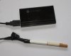
First, connect the battery to the atomizer and get ready to use the lighter. Your goal is to melt the glue that is holding the gold color adapter and the battery together.

Holding on to the atomizer side, slowly ROTATE the e-cig over the flame of the lighter on the battery side of the e-cig for 10 seconds(Silver part is the atomizer, black is the battery).


With medium strength, slowly wiggle and pull the atomizer away from the battery. If this fails, don't force it, just heat it for another 5 second and try again. It should come apart without too much force. Repeat if necessary. I have destroyed 3 connectors by forcing or wiggling too hard.


Next, you want to unsolder the red and green wire from the battery connector.


Now do the same lighter trick on the other end of the battery but with 3-5 second duration over the flame. Then use a screw driver and try to punch the end cap out.


Now we are going to prepare the tactile switch. You can use the shorter 5mm instead of this one. It a personal preference.


Cut the two end off as shown in the picture below with the small wire cutter. Then file the remaining stubs (with the disposable nail filer) so we won't have issue with shorting later.


Now prepare two length of wire about 1 inch longer then the battery tube itself along with 1/2 inch of shrink tubing (can use small piece of duck tape as replacement)


Bend the remaining two pins on the tactile switch underneath, then put a small bit of solder onto both end of the wire and the switch.


Last edited:

opusMorian

Senior Member
ECF Veteran
Feb 14, 2009
84
1
Houston, TX
Now wire both wire to the switch and electrical tape the bottom of the switch. Now be careful to wrap it around at least twice so the exposing pins won't make contact with the metal battery tubing later.


We are now going to prepare the USB cable. I had a set of belkin cables that were thin enough for this job. You can also use a Jawbone USB cable charger like the one in this link New Jawbone USB Cable Charger Aliph Bluetooth Headset @ - eBay (item 150336739251 end time Apr-04-09 11:12:40 PDT)

It has to be thin so it can fit in with the tactile button. If someone has a better/cheaper source for this, please let me know.


Strip the cable to expose the positive and negative wires. Use a voltage meter to test which is the positive and negative. In this case, it was red positive and blue negative. We want to cut off all the other wires but cut them one at a time and at different length so we reduce the chance of grounding.


Now put the shrink tube in one of the tactile button (does not matter which one) and solder that to the ground wire (blue). We then shrink the tube to secure the connection (or electrical tape it)


Now bend the ground wire we just soldered 180 degree and insert it through the empty battery tube.


Now we are going to connect the gold battery connector onto the wire. The positive (Red) to the middle of the connector and the negative (Blue) to the outer part (inside of the ring, not the outside)


Now we want to fit the gold connector on the battery tube, but don't secure it yet, just enough so that if something went loose, we can re-solder.


Next we are going to gently insert the tactile button into the other end of the battery tube. With the electrical tape, it should fit snug inside while the usb cable fit on the small opening on one of the sides. Make sure the tape does not come off or you will ground (activate) the device and it will stay on always. Now you see why we need a thin usb cable?


We are almost done, plug in your device and use the voltage meter to make sure its outputting 4.5v to 5.0v when you press the tactile button. If now, take everything apart and make sure everything is soldered correctly.

After everything is tested, plug in your atomizer and give it a try. As a warning:
1. don't hold the button down for more then 5 seconds since you might burn out your atomizer.
2. Don't let your atomizer go dry
3. If the atomizer stay hot when you release the button, you have a short somewhere!!! Unplug the USB and test all your connections. If you did not tape the tactile switch tightly, the small pin on the switch might pierce through he tape and make contact with the metal battery tube.
4. Some USb ports might not be USB 2.0 and output enough voltage. Some even have voltage protection that will turn off the USB port. Check for error messages on the lower right hand of your windows taskbar for warning messages.

After a few more test, secure the gold connector tightly onto the battery tube.

BAM! You are done!


Another note, one of the IO wire for the USB can be confused with the ground wire. It will show 4.5-5.0 volts when connected but will not work when you insert the atomizer. Sometimes the ground wire are the ones not shielded and if you having problem finding the ground, try the un-shielded one.


I want to give a big thanks to those generous individual who donated their batteries to me. It gave me a chance to fearlessly disassemble them for learning.

Hope this help someone, I am currently working on a screwdriver clone. I have done the prototype, but still in the process of looking for accessible part (radioshack, home depot) that anyone can purchase. Stay tuned!
 
Last edited:

opusMorian

Senior Member
ECF Veteran
Feb 14, 2009
84
1
Houston, TX
I know this is probably something you already thought of, but with radio shack part 275-1571 Submini Pushbutton Switch, I was thinking of something like this:

graphic1s.jpg


The part part around the led is a led holder. Radio shack has a variety of LED holders. You can probably find one with a outer dimension that will fit inside your tubing. Issue is that you probably need a voltage regulartor/step down since more common leds are around 1.5 volts. Also by adding 1.5 volts, you are taking away power from the atomizer. if you found a solution for that, I would like to know that also.
 
Last edited:

Fox3

Senior Member
ECF Veteran
Mar 24, 2009
281
1
Seattle, WA
As I type, I am into the process of making a USB Passthrough for an 801 :).

Thanks to these instructions I got the battery apart just fine. It is a good one so I'll save it for when one dies so I can rebuild it :).

Dug out a switch that looks VERY similar to what you have there and just happened to have the stock number for it from Digikey. Looked it up and the switch is rated at 0.05A (50 mA) at 24V (DC I would assume).

IIRC, the passthrough is expected to draw ~1A (~1000 mA). Or at least the USB Hub is expected to supply that much (mine will do 2A with the plug in power supply) or 0.50A (500 mA) as a normal USB port puts out (depending on device requirements, of course :).

Am I confused?

The one on the 510 manual battery I can't imagine would be huskier than that.

I have a switch rated for that but it sure is a LOT bigger :).

If this is working for you it is good news. Any problems with it so far and have you possibly measured the current draw?

Thanks very much!
 

opusMorian

Senior Member
ECF Veteran
Feb 14, 2009
84
1
Houston, TX
As I type, I am into the process of making a USB Passthrough for an 801 :).

Thanks to these instructions I got the battery apart just fine. It is a good one so I'll save it for when one dies so I can rebuild it :).

Dug out a switch that looks VERY similar to what you have there and just happened to have the stock number for it from Digikey. Looked it up and the switch is rated at 0.05A (50 mA) at 24V (DC I would assume).

IIRC, the passthrough is expected to draw ~1A (~1000 mA). Or at least the USB Hub is expected to supply that much (mine will do 2A with the plug in power supply) or 0.50A (500 mA) as a normal USB port puts out (depending on device requirements, of course :).

Am I confused?

The one on the 510 manual battery I can't imagine would be huskier than that.

I have a switch rated for that but it sure is a LOT bigger :).

If this is working for you it is good news. Any problems with it so far and have you possibly measured the current draw?

Thanks very much!

Just tested with a multimeter and it is drawing 1A like you said. I have been using this for about a week. I previously build (using the word "build" loosely here sine it was all electrical taped together) one with the radio shack size N panel mount plug and have been using that for about 2 1/2 months without major issues other then the tape falling apart. The tactile switch I used in this DIY is 50ma like the one you found but at 12vdc.
 

Catanonia

Super Member
ECF Veteran
Apr 3, 2009
416
13
UK
extraview.dnsalias.com
nice work there.

I had a passthough with inline battery arrive from a supplier and it was pants.

Sometimes worked, sometimes didn't

My mod just works all of the time with a constant 5volts supplying the atty.

It has recovered 2 attys by burning off the crud so I am 2 attys up at the moment.

Going to make another one for spare this afternoon :)
 
Status
Not open for further replies.

Users who are viewing this thread