
You are using an out of date browser. It may not display this or other websites correctly.
You should upgrade or use an alternative browser.
You should upgrade or use an alternative browser.
Easy recharge
- Thread starter crazyhorse
- Start date
- th_trl_thread_readers 0
- Status
- Not open for further replies.

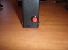
Really simple. Hook the black wire to the black screw and hook the red wire to the red screw. Just like jumper cables. When the red light goes to green, it's done. The terminals also provide a handy point for a quickvoltage check
with a meter.
Haha! that's tight!
That can be taken a mini-step further... just add the terminals to the top and bottom of one side of the case, and the whole box can be set into the charger without the need for wires, and the checkpoints for voltage would still be accessible. Could even do away with ruining one side of the charger. I might just try this... Thanks Crazyhorse!
That can be taken a mini-step further... just add the terminals to the top and bottom of one side of the case, and the whole box can be set into the charger without the need for wires, and the checkpoints for voltage would still be accessible. Could even do away with ruining one side of the charger. I might just try this... Thanks Crazyhorse!
Scratch that.. seems the battery box just barely fits, and I imagine that if there were terminals poking out even the slightest bit, the box would no longer fit in the charger... that's unfortunate really...
It would almost work with the terminals on the sides. There's plenty of room in the charger for that orientation but there are a couple of problems. 1) The battery box isn't comfortable standing up in the charger. It likes to flop. 2) That level inside the box is slammed full of structure and switch.
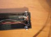
The charger isn't affected by the wiring. It's temporary. The positive connection to the charger is a slightly modified 12 ga .... connector. I cut the hard plastic sheathing back by about a ¼" and changed the shape from round to racetrack. The wire is crimped into the other end. It plugs right into the slot immediately south of the "official" positive terminal.
The charger isn't affected by the wiring. It's temporary. The positive connection to the charger is a slightly modified 12 ga .... connector. I cut the hard plastic sheathing back by about a ¼" and changed the shape from round to racetrack. The wire is crimped into the other end. It plugs right into the slot immediately south of the "official" positive terminal.
It would almost work with the terminals on the sides. There's plenty of room in the charger for that orientation but there are a couple of problems. 1) The battery box isn't comfortable standing up in the charger. It likes to flop. 2) That level inside the box is slammed full of structure and switch.
I was thinking something along the lines of a walkie talkie charging station. I can't post links yet (and i'm not positive the attachment will show up until after I post) ... a quick google image search and you'll see what I'm talking about, though it sounds like we're on the same page.
Just set the battery box down in the charger (which may have to be modded - ahh boo
 ) and when the green light comes on, it's vape time. This would allow for using the screw to really lock up the box and not have to worry about the cover coming off, even though so far, that's not a problem. Eventually though, it will probably wear from opening and closing and no longer snap into place.
Attachments

Last edited:
It only takes something like two seconds to complete the cable hookup. Not a big deal and a hell of a lot quicker than popping the cover, extracting those big@$$ batteries out of their tight@$$ compartments and then putting it all back together again.
My battery box is screwed shut and now it can stay that way.
My battery box is screwed shut and now it can stay that way.
This battery pack (with three AA size 3.7v 900 mAh protected Trustfire 14500 cells) survived 3½ days of use @ 17 hours per day @ an estimated average of 2 ml per day. I puffed it to the point of total vapor depletion. In the final half hour or so, vapor gradually began decreasing. At the point where it refused to give up another puff, a voltmeter read 0.98v from the pack. This appears to be way outside of spec for lithium batteries.
The battery pack required 5:45 for recharging to the green light cutoff point of 4.17v. This was at the 450 mAh rate represented by the charger documentation.
The battery pack required 5:45 for recharging to the green light cutoff point of 4.17v. This was at the 450 mAh rate represented by the charger documentation.
You could easily make a modded adapter for your charger that would fit your box into it. Granted that you may be willing to mod the charger, unless you are using it for something else too...
The main use for the charger is doing single cells so I wouldn't want to modify it. It would be cool to simply drop the big box into it but hooking up the jumper cables is so simple it's not worth the trouble to do anything else right now.
When I break this 3 x AA box and build another one, I'll probably build it to dock. It wouldn't be that hard. Flatter terminals on opposing sides and taking a moment to balance the box when placing it in the charger is all it would take. That configuration wouldn't be a workable solution for charging in the car on a long road trip but it's not a big deal with a pack that lasts for days.
When I break this 3 x AA box and build another one, I'll probably build it to dock. It wouldn't be that hard. Flatter terminals on opposing sides and taking a moment to balance the box when placing it in the charger is all it would take. That configuration wouldn't be a workable solution for charging in the car on a long road trip but it's not a big deal with a pack that lasts for days.
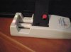
Ok.. this was pretty easy, but the terminals don't match up very good with the points on the charger. I'll probably have to add something to the postive terminal on the charger so the contacts will work, but this is definitely do-able.
Attachments
Ok.. I was trying to figure out a way to do something with the Ultrafire charger, but never thought to look at my TrustFire charger. The Trustfire works great with no modification except for cutting away a bit of the plastic around the positive termal (the side where the cord plugs in). I'm sure this could even be avoided if I had placed the screw head a tiny bit more towards the bottom of the battery box. Space is extremely limited due to the main switch (which i managed to fill with the epoxy..)
Also, if you are going to build this, make sure you find a small enough screw to work with, but mainly, find one that is EASY to solder to. If I knew more about soldering, I think this part would have been less frustrating for me. (solder was not staying, well, soldered...)
I have this nice digital camera and still can't figure out how to take good clear pictures every time...
Attachments
Really simple. Hook the black wire to the black screw and hook the red wire to the red screw. Just like jumper cables. When the red light goes to green, it's done. The terminals also provide a handy point for a quickvoltage check
with a meter.
This is so smart. Could this be done with cr2 batteries and charger? If so where would you hook the cables?
This is so smart. Could this be done with cr2 batteries and charger? If so where would you hook the cables?
I don't see why you couldn't. All you have to do is tie external charging terminals into the positive and negative circuits of your mod box and connect those to the respective terminals on the charger.
NomasTomas,
Interesting workaround you came up with for the UltraFire charger.
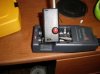
Thanks! It was really all your idea. I found an extra dc jack and had one more battery box and decided to try. The philips bit added a little too much spacing, and was tricky to get in just the right position, but did seem to work. I think with the ultrafire chargers, you will have to sacrifice one of the channels, but should still be able to use the other one just fine. As long as the charges last, and as fast as the batteries charge, this shouldn't be a big deal.I don't see why you couldn't. All you have to do is tie external charging terminals into the positive and negative circuits of your mod box and connect those to the respective terminals on the charger.
NomasTomas,
Interesting workaround you came up with for the UltraFire charger.
Seriously, how do you identify screws that can be easily soldered? Small screws.. with flat heads.. that would be perfect. Panhead screws would probably interfere with the cover as well. Did I mention space is very limited?
Tomas, for the room you have to work with, I'd suggest 3 mm screws and hex nuts. Screws that are appropriate would be of the type used to screw down a motherboard or for securing add-on cards to a computer case. You could just wrap your wire behind the nuts and wouldn't even need to solder.
With the terminal orientation I used, space was not a problem. I used 3 mm machine screws and some brass hex barrels I found in my bag of miscellaneous computer screws and junk. These hex barrels are 6 mm x 10½ mm. They have a 3 mm female thread at one end, an unthreaded hole at the other end and a slot through two of the flats. I guess these are actually some type of motherboard spacers. To connect my wires, I laid one in the slot and soldered it in. The other, I soldered into the end hole. From there it was simply a matter placing the barrels over the holes in my box and screwing them in place.
The thing I like about the way I set mine up is I don't have to muck around with the charger at all and don't have to sacrifice a channel. Three alligator clips, two pieces of wire and one .... connector is all it takes.
Last edited:
Seriously, how do you identify screws that can be easily soldered? Small screws.. with flat heads.. that would be perfect. Panhead screws would probably interfere with the cover as well. Did I mention space is very limited?
I'm thinking that a 1/8 pop rivet would be about perfect. Very low profile on the outside and would take little space on the inside. By using a 1/8 washer on the inside you could easily place the wire between the washer and case avoiding the need to solder. It should provide a good mechanical connection that way. I'd use the aluminum ones cause their cheep, but you can also get them in stainless steel if your want.
i have an idea make something such as 2 screws in a piece of plastic or wood that would get a contact with the charger put wires on then tape it or what ever then run them wires into an old atty connector and make it so u just have to turn on the switch and clip down the button and screw on the connector so that the box still looks stock i would give it a go but im using 3x duracell batteries (1.2v 2000mah) and you have to have 2 batteries in the charger to make it activate one side (2 sides) but if i ever get a charger that looks like them then il try it out... unless i can make one that will plug into two of them to make it activate mine too gets over 3 days of vaping never ran it completely down but after 4 days i think i noticed a small decrease in vapor... maybe lol idk but ima give it a go il find a suitable thing to hold the button down too
make something such as 2 screws in a piece of plastic or wood that would get a contact with the charger put wires on then tape it or what ever then run them wires into an old atty connector and make it so u just have to turn on the switch and clip down the button and screw on the connector so that the box still looks stock i would give it a go but im using 3x duracell batteries (1.2v 2000mah) and you have to have 2 batteries in the charger to make it activate one side (2 sides) but if i ever get a charger that looks like them then il try it out... unless i can make one that will plug into two of them to make it activate mine too gets over 3 days of vaping never ran it completely down but after 4 days i think i noticed a small decrease in vapor... maybe lol idk but ima give it a go il find a suitable thing to hold the button down too Just take a small pill bottle drill a hole in each end, mount brass screw in end and cap with nuts to hold them in place, drill hole in center of bottle, stick wires through center of bottle connect wires to pushon connectors, plug them on screws, screw cap on, and mount 1/8 inch phone jack RS 274-0287 so you can plug into mod. Use 1/8 inch panel mount phone jack RS 274-251 in mod. Pop pill bottle mod in charger and plug into mod done. You can see panel phone jack in my mod at 2 cell phone batt mod on my other post. This can also be done with a small peice of pvc pipe and some JBW to hold screws in ends of pvc pipe, works great for me. I got this from anouther modder this was not my idea but its a great idea!
- Status
- Not open for further replies.
Similar threads
- Replies
- 43
- Views
- 4K
- Replies
- 15
- Views
- 3K
- Replies
- 7
- Views
- 808
- Replies
- 54
- Views
- 6K
Users who are viewing this thread
Total: 2 (members: 0, guests: 2)