GnarlyCharlie4u's - 5v bottom feeder in a 3xAA box mod

Status
Not open for further replies.

paperassgasket

Full Member
Mar 1, 2012
16
3
39
22192
So I'm trying to build a 5v bottom feeder and cram it all into a 3xAA.
It's a tight squeeze as it is and I've run into a couple problems so far, but I think this can be done once I hammer out all the bugs.

First up, I did this:
I scavenged.


I debated on actually using the button part of the controller button, or just have the exposed circuit board be the button.
The switch can be really high resistance because of the mosfet, so it's possible to use your finger to bridge the two connections. After soldering I decided to just use the button to hide it. Plus it'll give you nice haptic feedback to let you know you're actually making a connection.


ACjWQ.jpg


UzyAl.jpg

Cut out the board sections with a boxknife


OZEiE.jpg

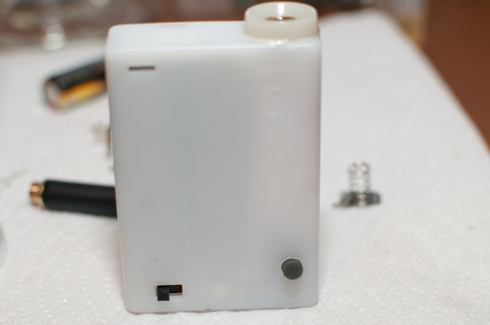
I need to drill a hole.


3Z8Jh.jpg


Need a drill bit small enough... I think .040" should work.

sxYnH.jpg


Nailed it.


XQCKe.jpg

Time to solder on the wires.
pq3BJ.jpg


Like a boss.

Ll92E.jpg

mzCOd.jpg

K37Tm.jpg


It should fit nicely and still allow room for an LED.


Vape - Imgur


V3cat.jpg

L3uVS.jpg


It worked awesome up until I glued everything in there permanently. I have no idea what fuxed up but I pulled it out and started over. It was all down hill from there and there was one problem after another with this box (broke a wire, broke an LED...)

lr9Do.jpg

JJCti.jpg


I rebuilt it a couple times, making improvements each time (until I gave up on it)

tZ5bk.jpg

v9Lvq.jpg

LHVoC.jpg

BZSoT.jpg

jr9b9.jpg

JnA7C.jpg

dvUsN.jpg

0pmcf.jpg

1UJUV.jpg

ehTNz.jpg


so I decided to build another box from scratch (as a control):

5RVaP.jpg

yO43Y.jpg

47tDD.jpg

sIC92.jpg

DFP9z.jpg

mXsM6.jpg


I goofed a bit when I made this second one. I used the wrong resistor on the LED so it won't light up. I need 2.5v to the led so I basically have to get a resistor to cut the voltage in half.


I'm having some problems with this one too though.
Sometimes it only vapes for a second before cutting off. I have to flip the switch off/on before it'll work again.

Also unlike the first one, I have to actually touch the wires together, instead of just using my skin (or some other high resistance thing) to bridge the connection.

I used this wiring guide to make it:
T00vf.jpg


So here we are, I have two 5v boxes that almost work and I can't figure out why...
If anyone has any suggestions or theories I'd be glad to listen.
I'll post more when I figure out what's going on.
 

paperassgasket

Full Member
Mar 1, 2012
16
3
39
22192
Whelp... make it 3.

I think it might have something to do with soldering causing resistance issues?
I breadboarded the whole circuit before I soldered it all together and it worked perfectly. As soon as I wired it all up and soldered it all together, the LED refused to light and the switch requires a very low resistance connection.

I am confused.
 

paperassgasket

Full Member
Mar 1, 2012
16
3
39
22192
Okay... I'm an idiot. I built and rebuilt all these boxes a couple times or more each before discovering that all my 510 atty's were dead.

Now I know why they'd work for about a day and die. :-/

Too bad madvapes doesn't have a warranty on their attys.
3 bad ones is some serious bad luck. 2 DOA and one worked for about a day before crapping out on me.
 

twohandedcreations

Super Member
ECF Veteran
Verified Member
Sep 19, 2011
527
450
45
orlando florida
I'm sure I'm not telling you anything you dont already know. Having to turn the on/off switch back and forth to get it to work again sounds like the protection circuit's in the batteries! when the atty res. is too low for 5V's those silver ultrafires will trip. It happens to me alot when i put an LR atty on one of my 5V'ers. Turning the switch on and off disconnects the batteries and resets the protection circuits. I'm just mentioning this because it seem's to me like it happens the most with my silver ultrafires. I have pretty much every kind of protected 14500 there is, and it seems like it happens with those the most!
 

wolcen

Ultra Member
ECF Veteran
Verified Member
Mar 9, 2011
1,182
1,302
Boston, MA
www.wolcen.com
Hi,

I'm a [lot] rusty on my electronics, and am trying to understand how your switch is working. The reg you have is the KA378R05 I believe, and I thought that you would place a normally closed switch going to that control pin? I guess I'm getting lost on how the resistor that's between control and gnd functions perhaps...

Great pics btw.
 

paperassgasket

Full Member
Mar 1, 2012
16
3
39
22192
Hi,

I'm a [lot] rusty on my electronics, and am trying to understand how your switch is working. The reg you have is the KA378R05 I believe, and I thought that you would place a normally closed switch going to that control pin? I guess I'm getting lost on how the resistor that's between control and gnd functions perhaps...

Great pics btw.
Yup the reg I'm using is the KA78R05
Here's a PDF that explains the circuit of the regulator:
http://www.datasheetcatalog.org/datasheet/fairchild/KA78R05.pdf
Offhand I can't say, I'm using someone else's wiring design. I think it allows me to use a normally open switch.
and thanks!

I'm sure I'm not telling you anything you dont already know. Having to turn the on/off switch back and forth to get it to work again sounds like the protection circuit's in the batteries! when the atty res. is too low for 5V's those silver ultrafires will trip. It happens to me alot when i put an LR atty on one of my 5V'ers. Turning the switch on and off disconnects the batteries and resets the protection circuits. I'm just mentioning this because it seem's to me like it happens the most with my silver ultrafires. I have pretty much every kind of protected 14500 there is, and it seems like it happens with those the most!

Yep I thought that might be the problem at first too but it was not the case. Both 5v boxes are up and running fine now; it was the attys.
 
Last edited:

wolcen

Ultra Member
ECF Veteran
Verified Member
Mar 9, 2011
1,182
1,302
Boston, MA
www.wolcen.com
Thanks for the followup!

Glad you resolved your issues - I'm going to try making it this way too then since I have everything on hand.

I like the catch cup/beauty rings you are using too. I'm playing with finishing washers at present...what is that you are using?

Sorry for not asking all my questions at once - I think I'm good after this :p
 

paperassgasket

Full Member
Mar 1, 2012
16
3
39
22192
Thanks for the followup!

Glad you resolved your issues - I'm going to try making it this way too then since I have everything on hand.

I like the catch cup/beauty rings you are using too. I'm playing with finishing washers at present...what is that you are using?

Sorry for not asking all my questions at once - I think I'm good after this :p

Nah they're actually plugs; like tunnel plugs for running wire. There's a hole in the middle that I can stick the LED in so it only lights up the bottle.
 

paperassgasket

Full Member
Mar 1, 2012
16
3
39
22192
So I built another box (actually 2 more :D) and tried the "broken" atomizers...

One trips the voltage regulator circuit and the other is now doing some weird stuff. It vapes terribly; low vapor and no flavor.

I'm wondering if the resistance on those is just bad. It seems like the one tripping the regulator is too low and the other is too high. I'll test them when I get home.

Confirmed... one spare atty tests out at about 1 ohm the other is 12.2ohms haha.

We used a 3.2ohm bauway on it and it works great.
I also just ordered a bunch of iVape 2.8's so we'll see how those do.


Thanks for the followup!

Glad you resolved your issues - I'm going to try making it this way too then since I have everything on hand.

I like the catch cup/beauty rings you are using too. I'm playing with finishing washers at present...what is that you are using?

Sorry for not asking all my questions at once - I think I'm good after this :p
I just realized what you were talking about. Yes those are finishing washers. #14's I believe.
Sorry for the confusion.
 
Last edited:

wolcen

Ultra Member
ECF Veteran
Verified Member
Mar 9, 2011
1,182
1,302
Boston, MA
www.wolcen.com
12 ohms... I'm thinking you may need just a few more volts LOL :p

OOOOk! Now we're on the same page. Conversely, I had no idea what you meant by tunnel plugs and said to myself "google search for those might not be easy...nor G-rated" :?:

Now I see that you were referring to the grommet you are using for a spacer below your bottle. Cool. I happen to have one of those on hand too though I have other plans for it.

Thanks again p.a.g.!
 

paperassgasket

Full Member
Mar 1, 2012
16
3
39
22192
OOOOk! Now we're on the same page. Conversely, I had no idea what you meant by tunnel plugs and said to myself "google search for those might not be easy...nor G-rated" :?:

BWAHAHAHAHAHAHA! good call...

So far the spacer is working out alright. It was perfect the first 2 times I built the box it's used in. After that though, things started getting messy and the new LED I put in there + the fact that I trimmed the outside battery contact holder makes the gromet sit cocked.
If you don't have to continually repair this box a bunch of times it should work out real nicely.

The plug/gromet thing I used has a hole large enough for a 5mm LED. Not only does this hold the bottle in there nicely but it means that the LED will ONLY light the bottle instead of making the whole box glow.

Although the door is not pictured (gave it away before I snapped a few), we opted to drill a small hole then use a small dremel sanding bit to make a rounded off rectangle for a squeeze hole. It's aesthetically clean and really complements the shape of the box.

My only real dilemma at the moment is where to mount the circuit board switch.
On the last box we just glued it to the short side of the box near the bottom. That seemed like a decent place for it but I feel like we could still find a cleaner and lower profile way of doing it.

Basically the whole goal here is to build boxes that are easily rebuild-able in the event that a component fails.
Hot gluing pieces in place does not make for an easily rebuild-able box.
 

wolcen

Ultra Member
ECF Veteran
Verified Member
Mar 9, 2011
1,182
1,302
Boston, MA
www.wolcen.com
Basically the whole goal here is to build boxes that are easily rebuild-able in the event that a component fails.
Hot gluing pieces in place does not make for an easily rebuild-able box.

If you figure out a component scheme for that, you gotta let us know...that's something I've been mulling over for a bit myself too. I'm thinking my first (or second, since the first one's usually a find/fix the design kinks effort) Altoids box mod will be the target of this a goal. When I get that done, I gotta get you to take the pics. These ones are about the clearest I've seen on ECF. :)
 

paperassgasket

Full Member
Mar 1, 2012
16
3
39
22192
If you figure out a component scheme for that, you gotta let us know...that's something I've been mulling over for a bit myself too. I'm thinking my first (or second, since the first one's usually a find/fix the design kinks effort) Altoids box mod will be the target of this a goal. When I get that done, I gotta get you to take the pics. These ones are about the clearest I've seen on ECF. :)

I'm also working on a couple other mods. One will be entirely modular, meaning any component can be simply unplugged and swapped out in a matter of seconds. I'm using the pin connectors and wires from computer motherboards for that. A 4 pin (red yellow yellow black) motherboard connector is the exact width and pin spacing of the 5v regulators available from madvapes.

The only problem with this design is going to be the amount of space required to keep things accessible as well as all the added wire and connectors. This might wind up being a 5v passthrough drip (not bottom feeder) for the desk.

I'll keep you posted though.
 
Status
Not open for further replies.

Users who are viewing this thread