Internal usb charging; best/safest method?

Status
Not open for further replies.

Rader2146

Ultra Member
ECF Veteran
Verified Member
Mar 11, 2012
1,197
1,033
Waco, TX
Here's my plan for internal battery charging:

This charger board:
eBay - New & used electronics, cars, apparel, collectibles, sporting goods & more at low prices

In this USB Enclosure:
P3A-201005U New Age Enclosures Enclosures, Boxes, & Cases

With this cable (cut to desired length):
Digi-Key Part Search

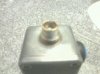
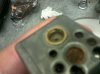
and this connector inside the mod:
http://search.digikey.com/scripts/DkSearch/dksus.dll?Detail&itemSeq=112193918&uq=634678976242898216

Now, granted, the charger itself is not in the mod but this will allow you to charge multiple mods with 1 charger assembly. All you have to buy is a $1 barrel jack per mod, instead of buying a $12.50 charger board per mod. This also saves valuable space inside the Mod. The barrel jack is only 9x6x5 mm (smaller footprint than a mini usb) leaving room for MOSFETs, regulators, large switches, etc.

400ma charge rate might be on the slow size for large batteries. I only plan to use this on 14500 or smaller bats. You could easily put a charger that is adjustable via resistors inside a small project box spliced into this cable.
 

bamsbbq

Super Member
ECF Veteran
Verified Member
Sep 24, 2011
956
707
Tacoma,WA
Here is mine. Made by rocketman.
With an 18650 battery
Can be charged through top.ego connector or bottom charging port with a slightly modifies ego-like charger.

Sent from my SPH-M820-BST using Tapatalk
 

Attachments

  • uploadfromtaptalk1332321942797.jpg
    uploadfromtaptalk1332321942797.jpg
    17.4 KB · Views: 57
  • uploadfromtaptalk1332322005837.jpg
    uploadfromtaptalk1332322005837.jpg
    15.4 KB · Views: 55

Beaverkt

Super Member
ECF Veteran
Mar 5, 2011
343
37
37
NC USA
Trying to do some research into building my first mod with on board charging. Looking at this charger
LiPo Charger Basic - Micro-USB - SparkFun Electronics

Am I correct in saying that all I need to do is wire in the postive and negative from the battery connections to the positive and negative on the board ? Or am I completely missing something ? Also If were to add this protection circuit

Tenergy 32002 Protection Circuit Module (PCB) Round for 3.7V Li-Polymer Battery 3.5A Working (6A cut-off)
that I would wire both the atty and the charger to p+ and p- while the battery itself would be on b+ and b- ?
 

CraigHB

Ultra Member
ECF Veteran
Jul 31, 2010
1,249
314
Reno, Nevada
You can exceed that using a "charging port". The USB spec defines charging ports with much higher current capability. 2A wall and cig lighter adapters are available. The 2A wall adapters I got from MadVapes perform well at their maximum rated output.

The lower current limits only apply to data ports. Many retail adapters are similarly limited in current output, but that's because of the maker, not the spec. The spec says any generic charging port should have a minimum output capability of 1.5A. Those 500mA wall adapters you see a lot are actually out of spec.

With a charging port, higher currents are not an issue as long as the adapter and cable can support it. My feeling is a charging port should always be used anyway. I'm not willing to use my computer as an expensive e-cig power supply even if the port is not overloaded.

If the ability to use a computer port is imperative, then the lower current limits can be an issue. But like I said, I think it's a bad idea to use one anyway.
 

Digital-Dragon

Super Member
ECF Veteran
May 12, 2011
360
236
I agree Craig. I always plan on using a usb wall adapter, not the computer. Though from my limited understanding of such things, it's only real passthroughs, and not a design like this that will sometimes fry motherboards. So it seems like the only issues with using a comp to recharge a 18650 via usb would be that it would take many hours? Or am I missing something?


Also, if anybody would like to post wiring diagrams related to on-board charging, feel free to do it here :)
I have made a few, but they are not not pretty enough to be worth sharing.
 

bamsbbq

Super Member
ECF Veteran
Verified Member
Sep 24, 2011
956
707
Tacoma,WA
Pm rocketman, he build my mod, with dual charging options. Charge off the ego connector or charge off a.charging connection for lack of better terms.


I am not sure what chip/board he used in mine but I can use mine as a passthrough as well

Uses an 18650 takes awhile to.charge if battery is dead but no worries its a PT. lol

Sent from my SPH-M820-BST using Tapatalk
 
Last edited:

CraigHB

Ultra Member
ECF Veteran
Jul 31, 2010
1,249
314
Reno, Nevada
...from my limited understanding of such things, it's only real passthroughs, and not a design like this that will sometimes fry motherboards.

That's typically true, but you can also overload a data port if using a higher charging rate. Most USB Li-Ion chargers charge at a rate of 500mA or less, but there are USB Li-Ion chargers available with a 1A rate. Personally, I use a USB charger with a 1A rate powered by a MadVapes 2A USB wall adapter.

So it seems like the only issues with using a comp to recharge a 18650 via usb would be that it would take many hours?

There are several issues. One is that a USB charger with a 500mA charging rate will take approximately twice as long as one with a 1A rate. Another consideration is a 500mA charging rate will not overload a data port where a 1A rate may overload a data port.

This doesn't apply in your case since you are using an 18650, but a consideration can be the tolerable charging rate for the cell. 1C is a safe assumption. You never want to go over that. Some Li-Ion cells can handle higher rates. IMR cells and high drain LiPos can typically handle 2C, but even so, it's best not to push them to the limit. For example, 1C for a 10440 with 350mAh, is 350mA. Even a USB Li-Ion charger with a 500mA rate would be too high. For a protected 14500 with 750mAh, a 500mA rate would be okay, but a 1A rate would be too high.
 

Digital-Dragon

Super Member
ECF Veteran
May 12, 2011
360
236
Thanks again, quite helpful info Craig.

I'm looking at a few usb wall adapters I have laying around, one is 5 volts 500mA (came with a riva) and the other is 5.1 volts 850mA.
I have one charging board coming that is a half amp, and one that is a half amp by default but I'll be using it at 1 amp. So I should probably not use the riva one for this at all, use the 850 for the half amp charger, and get the madvapes one for the 1 amp charger? Seems like that would work.
But if I was to use the 850mA wall adapter with the 1amp charger board, the only "negative issue" would be that it would take longer to charge, right?

Edit: Just found a 1050 mA wall adapter... Would that work as well as the 2 amp madvapes one for use with a 1 amp charger? or am I missing something?
 
Last edited:

CraigHB

Ultra Member
ECF Veteran
Jul 31, 2010
1,249
314
Reno, Nevada
You have to be a little skeptical about wall adapter ratings. I bought a couple cheap USB wall adapters with a 1A rating that sagged in voltage miserably at 1A. They ended up in the trash. For any application, you usually want a power supply with a much higher current rating than actually required. That way, the power supply will not be heavily loaded and voltage will not sag much.

A USB charger that uses a 1A rate will in fact draw 1A from the supply plus a half tenth of an Amp or so in overhead. The draw tapers off once the cell reaches terminal charging voltage, but that's only toward the end of the charge cycle.

Most chargers engage an under-voltage lockout if supply voltage falls below what is required to charge a cell at the programmed rate. In other words, the charger may just shut down when attempting to power it with an inadequate power supply. Or, it may charge at the normal rate, then shut down at some point prematurely. This can happen since voltage demand from the supply increases as the cell gains more charge.
 
Last edited:

Digital-Dragon

Super Member
ECF Veteran
May 12, 2011
360
236
I understand now! Though that's not what I wanted to hear...

I think I'm leaning more towards sticking with the 500mA charge rate, and just dealing with the slower charge time. The more I learn about all this, the more sense that makes to me in multiple ways: It would be safer to charge from a computer if I was even so inclined, I would have a wider selection of usb wall adapters, and since I'm not the heaviest vaper I bet the charge time won't be all that long, as I'll be recharging every night when the battery is still mostly charged. What's your opinion on the direction I'm leaning?

Also, I have read many many different things about how we should be charging, as far as waiting until fully drained (which I never seem to do) or topping off every night. I like the idea of just topping off, especially since I've read fully draining them can be bad, though I've also read it can be good, like "conditioning" them, though I know they have no "memory effect." (talking about li-ion and li-mn)
 
Last edited:

CraigHB

Ultra Member
ECF Veteran
Jul 31, 2010
1,249
314
Reno, Nevada
Your charge rate is going to be a personal preference. 500mA is most flexible, but slower. 1A is almost twice as fast, but you're pretty much limited to a USB charger adapter of some kind. Personally, I like the faster rate. That way, I can vape and charge at the same time and still fully recharge in a reasonable amount of time. However, if being able to use a data port or an adapter with a lower rating is more important than how long it takes to charge, then the lower rate would be better.

There is no charging regiment with Li-Ions. You can charge them to any point at any time without a significant loss in longevity.

The one consideration is that shelf wear is increased when the cell lives at a higher level of charge most of the time. For a battery passthru, it's actually better to let the cell cycle a bit rather than keep it plugged-in all the time. Conversely, Li-Ions wear a little less when they are not discharged as deeply.

You'd pretty much have to do an in depth study to figure out a charging regiment that would result in absolute least wear. As a reasonable approach, I'd say it's best not to leave them fully charged all the time and when convenient, recharge them a little early. Though, it's not going to make a huge difference.
 

Digital-Dragon

Super Member
ECF Veteran
May 12, 2011
360
236
Excellent, that is what I wanted to hear!

So, change of subject. I'm looking at protection pcbs and I'm wondering if 1 amp or 2 amp is bettter for the current limit, (I'll probly be using only imrs, but maybe protected li-ion.) Also as far as overcharge/overdischarge, what are the specs of imrs? I can't seem to find them, though I know I've seen them in the past. Would 4.25v/2.3v be acceptable for imrs on the pcb?

Edit: good random imr info here: What exactly does "IMR" mean?
 
Last edited:

CraigHB

Ultra Member
ECF Veteran
Jul 31, 2010
1,249
314
Reno, Nevada
Your protection PCB should cover the drain limit of your cell. For example, an 18650 with 5A drain limit would call for a 5A protection PCB or the closest available under that. Generally, IMR cells do not come with built-in protection since the higher drain limits make it impractical. IMR cells are typically 8C so a 1600mA cell would have a 12.8A drain limit. That's not always the case though. Drain limits are specified by the maker. For example, the AW IMR 2000mAh has a 9.8A drain limit, but the AW IMR 1600mAh has a 12.8A drain limit. Always check the specs for the particular cell you are using.

Minimum discharge voltage depends on the particular cell. All Li-Ions drop off pretty quick once they get below 3.3 to 3.5V (open circuit) so there's no real benefit in taking them much below that. 3V is a safe cutout level for any 3.7V cell. Protection PCBs are not really meant to be relied upon in a routine fashion so the cutout is lower than ideal. It's generally assumed other electronics are present to routinely avoid over-charging and over-discharging. You may want to incorporate your own shutdown circuitry that keeps to keep the cell from dropping below 3V. If that's not possible, a protection PCB with a 2.7V cutoff would probably be okay for most cells.

Just about all 3.7V Li-Ions have a 4.25V absolute maximum. That derives from standard tolerance which is 4.20V nominal plus or minus 50mV. There are some obscure 3.7V Li-Ions that charge to 4.35V nominal, but you probably would not come across one. Protection boards normally have a 4.30V cutout so there should be no question there. It would not be possible to protect the cell from anything over 4.20V exactly due to standard charger tolerances. It would confuse the charger (and the user) if the cell cut out before the charger completed its cycle. The absolute minimum cutoff has to be 4.25V, but you need another 50mV for protection PCB tolerance. Hence, 4.30V.
 

Digital-Dragon

Super Member
ECF Veteran
May 12, 2011
360
236
Specs of the imrs I like:
AW IMR 18650 3.7v 2000mAh
Nominal Voltage : 3.7V Capacity : 2000mAH Lowest Discharge Voltage : 2.50V Standard Charge : CC/CV ( max. charging rate 2A ) Cycle Life : > 500 cycles Max. continuous discharge rate : 10A Operating Discharge Temperature : -10 - 60 Degree Celsius

This is the protection Pcb I'm thinking of using with that imr:
Prevents 3.7V Li-Ion Battery pack from overcharging 4.25V Prevents 3.7V Li-Ion Battery pack from over discharging 2.3V Maintains 3.7V Li-Ion Battery pack's discharge current lower than 1.0A. Protect battery from short circuit and wrong polarity

Or would this be bettter?:
Manufacture Part# PCM-Li01S3-107 Keep 3.7V Li-Ion Battery pack from overcharge beyond 4.30V +/-0.05V Keep 3.7V Li-Ion Battery pack from over-discharge below 2.4V +/- 0.1V Keep 3.7V Li-Ion Battery pack 's discharging current < 2.0A Protect battery from short circuit and wrong polarity

I gather that I need to use a protection pcb that is the closest to matching the battery I want to use, and it seems to me the first one I listed is fairy close... Is it close enough, or should I keep looking for something that matches exactly?

Edit: I got those protection pcb specs from the link provided by madmanmacguyver on page 2 of this thread.
Battery Management system

Edit: the first one has a 1Amp current rating, the second has a 2Amp current rating. That still confuses me...
 
Last edited:

Digital-Dragon

Super Member
ECF Veteran
May 12, 2011
360
236
I'm re-reading your last post Craig, and it seems like neither of the protection pcbs I listed are ideal for an imr... Do you have a link to something bettter for my purposes?

You've been very helpful. I really appreciate it, and I apologize for being a slow learner. Should have taken electronics instead of drafting in high school... I'm understanding a lot more about this stuff though, so it's all good :)

Edit: Okay, so this one has an 8A rating, seems a lot closer, but still might not be good enough? http://www.batteryspace.com/PCB-for-3.7V-Li-Ion-Battery-8.0A-limit.aspx and this one is 10A, but says it's for 3.6v not 3.7v cells? http://www.dealextreme.com/p/charge...hargeable-li-ion-batteries-17-4mm-1-9mm-26112
 
Last edited:

CraigHB

Ultra Member
ECF Veteran
Jul 31, 2010
1,249
314
Reno, Nevada
I was going to reply yesterday, but didn't get to it. I was actually going to link to this this one which is similar. The over-discharge is low, but it's high enough to keep the cell from getting damaged heavily (the lower cells are discharged the faster they wear).

DealExtreme is sketchy. It's a Chinese retailer so even if they get things out quickly, it takes a long time for shipping. The board they show has a definite lack of specifications listed so who knows.

Of course, the easiest thing to do is just use a protected 18650. Unless you plan to run a booster, there should be no reason why you wouldn't be able too.

Usually, a protection PCB is only required if you want to use a non-standard Li-Ion cell of some kind. Otherwise, just use a protected cell. Though, it's never a bad idea to add protection for an IMR cell. Some pople are under the mistaken impression unprotected IMR cells are perfectly safe. They are not. They should be protected when possible, but since the chemistry is "safer", it's less risky to use them unprotected. I would avoid running an IMR cell with no protection myself.

Keep in mind production boosters like the LavaTube and Pro-Vari that call for IMR cells comprise protection for the cell within the mod's electronics so it's already covered with those.
 
Status
Not open for further replies.

Users who are viewing this thread