Well, for my first two mods I want to start with the basic(maybe add a LED in) NicoStick, and then make a sort of USB capable flashlight mod with either a straight bypass to USB or make it have a built in charger.
So for the first and simplest, the NS, I would just need everything he has in his guide. I totaled it out and it comes to about $28 with an extra battery and the cheapest charger.
Now I also want to get the AC and Car to USB chargers(in the passthrough section), so I can get the corrcect amperage for vaping a 5v passthrough on the go. I might also purchase the 510 Sit and Go USB Passthrough to either use or tear apart for my own passthrough.
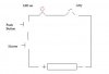
Now I get the general wiring for it, I just have to make the circuit complete.
but if I wanted to add the LED in to light up after I press the button to fire the atty would it be as simple as the nicostick attachment?
Or is there something I have to add in there so the LED will work? Hopefully its just simple =\
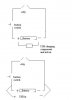
Now for the second one, I'm not sure if my crappy version of the wiring diagram makes sense, but I'm wondering if it would work(either one)
My goal is to make it work as a normal flashlight mod when un-plugged but when its plugged in, either make it go straight to a passthrough @5v, or make it charge the battery and work off of the battery as a passthrough like a lot of ones actually do. Or if I even could, have it plugged in and charge the battery, while vaping at 5v?(one can dream) But if it can't plug in, charge, and 5v vape, could I get it to work as a 5v pt while I take the battery out to recharge it seperately?
ECF should have never let me come to the modders forum, cause now you guys will never get rid of my extremely long questions =[
thanks in advance for any help =]
So for the first and simplest, the NS, I would just need everything he has in his guide. I totaled it out and it comes to about $28 with an extra battery and the cheapest charger.
Now I also want to get the AC and Car to USB chargers(in the passthrough section), so I can get the corrcect amperage for vaping a 5v passthrough on the go. I might also purchase the 510 Sit and Go USB Passthrough to either use or tear apart for my own passthrough.
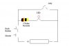
Now I get the general wiring for it, I just have to make the circuit complete.
but if I wanted to add the LED in to light up after I press the button to fire the atty would it be as simple as the nicostick attachment?
Or is there something I have to add in there so the LED will work? Hopefully its just simple =\
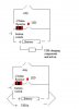
Now for the second one, I'm not sure if my crappy version of the wiring diagram makes sense, but I'm wondering if it would work(either one)
My goal is to make it work as a normal flashlight mod when un-plugged but when its plugged in, either make it go straight to a passthrough @5v, or make it charge the battery and work off of the battery as a passthrough like a lot of ones actually do. Or if I even could, have it plugged in and charge the battery, while vaping at 5v?(one can dream) But if it can't plug in, charge, and 5v vape, could I get it to work as a 5v pt while I take the battery out to recharge it seperately?
ECF should have never let me come to the modders forum, cause now you guys will never get rid of my extremely long questions =[
thanks in advance for any help =]