
Appreciate the reply, Ralph - I'm playing around with modeling the circuit in a SPICE simulator, now - they only had the irf520 in the database, though
You are using an out of date browser. It may not display this or other websites correctly.
You should upgrade or use an alternative browser.
You should upgrade or use an alternative browser.
Touch sensor switches
- Thread starter crazyhorse
- Start date
- th_trl_thread_readers 0
- Status
- Not open for further replies.
mnealtx,
Yes thats correct on the + & - connections. The "arrows" at the bottom of the resistor and the S (source) of the FET would be your ground (5v negative)
The diode in the FET will drop your 5v to abt 4.3-4.4v.
Using 5v and a 3.4ohm coil the current draw would be 1.47A.
It's well within those limits with 3.8A continous and 24A surging.
As far as the FET in the drawing, I said I didnt have a chance to spec it.
I was tryng to get you guys something to get you going.
Kender,
If you look at a previous post of mine a few back you'll see I made a reference to a schematic I thought I saw here. I had no intention of stepping on your find.
There just seem to be a lot confusion and frustration I was trying to help out with.
Appreciate the info, vaporer - just wanted to make sure I was straight.
I'm trying to figure out now how to make it where the regulator is NOT getting voltage until the FET is active. Not sure I'm even using this damn simulator software right...
I'm trying to figure out now how to make it where the regulator is NOT getting voltage until the FET is active. Not sure I'm even using this damn simulator software right...
If the FET you are using can use full battery voltage, you can wire the + of the regulator to the output of the FET, have the FET power up the regulator and move the atty to the regulator output.")
Basically, if you have the 5v regulator in now, power it up with the FET.
Basically, if you have the 5v regulator in now, power it up with the FET.
Vaporer, not how I felt at all. I liked the one that you posted better with the extra resistor to protect the FET in case the contacts short together.
The gate is fairly high impedance - it doesn't need protection.
If the FET you are using can use full battery voltage, you can wire the + of the regulator to the output of the FET, have the FET power up the regulator and move the atty to the regulator output.
Basically, if you have the 5v regulator in now, power it up with the FET.
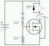
Ok... I modifed a drawing found here to show what I *think* I should have (attached) - do you agree? Unsure if the blocking diode would be needed, I saw it recommended on another page to prevent back voltage when the power comes off the atomizer coil.
Attachments
Last edited:
mnealtx,
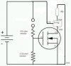
1st, you wont need the diode. The coil has no metal core like a transformer and will not "ring back" since no magnetic field is produced.
If you are using the 7805 regulator it would work like this.
The FET won't come on till activated and when it does it completes the GND circuit that turns on the regulator and heats the coil at 5v.
Attachments
Last edited:
Hey, Vaporer - thanks for the reply.
Modeled your circuit at lunch - constant voltage to the atomizer. There's still something screwing about the modeling of the other circuit, as well - the voltages are all wrong when probing the circuit.
Some redesign is in order, I think...just have to figure out the glitch.
Modeled your circuit at lunch - constant voltage to the atomizer. There's still something screwing about the modeling of the other circuit, as well - the voltages are all wrong when probing the circuit.
Some redesign is in order, I think...just have to figure out the glitch.
WOOHOO....Here we have my first touch switch. I have not etched my boards yet ...I want to make sure the MOSFET work the way I thought it would
The penny is there to show the size of a SOT23-6 chip

ad2covert - That board is only .34 x .46"
The penny is there to show the size of a SOT23-6 chip
ad2covert - That board is only .34 x .46"
Nice work there.
You could use a smaller watt resistor(1/10 watt), solder the FET to it with wires and just put a drop of epoxy on it.
Be much smaller...........hee hee
You could use a smaller watt resistor(1/10 watt), solder the FET to it with wires and just put a drop of epoxy on it.
Be much smaller...........hee hee
Thought about that but I am going to make a custom pcb with a usb charge chip aad touch switch. My PCB is 1.5" x 0.46'
That was the easiest resistor to use tonight. The resistors on the board are package 0805(very small)
That was the easiest resistor to use tonight. The resistors on the board are package 0805(very small)
I had to post this. First post on youtube ever. While watching this think of the Castaway sceen when Tom Hanks get the fire started
YouTube - Ecig touch switch
YouTube - Ecig touch switch
Yea, I have some resistors that will fit(SMD) between the pins. Very easy to be eaten by the solder. I make special solder tips for those.
Not recommended for a beginner for sure.
I get a little time, I might make my next mod a touch switch and post the "zoom" pic version so the ones here with a less technical background can join in on the fun.
Everyone wasn't raised with a degree in electronics and a soldering iron in hand.
So, lets help if and when can.
I am seriously thinking of using solder paste and just baking it in the oven. I have never soldered before finding this forum. I do have the benefit of working with a couple electrical engineers. I am a IT Systems Administrator.
I will post so close ups when I have the PCB etched.
Here is the whole this...Touch sensor switch and usb charger

As long as there is a battery in the box it will work while the battery is charging. Similar to a passthru.
Cheers
I will post so close ups when I have the PCB etched.
Here is the whole this...Touch sensor switch and usb charger
As long as there is a battery in the box it will work while the battery is charging. Similar to a passthru.
Cheers
Why not have your friends give you some pointers on soldering?
361* is gonna be tough on that little part if you are using Rat Shack silver solder and an oven.
Pre cut your leads to length and bent to fit. Tin them.
Clean your tip and just do a "touch and go" 1-2 sec then off.
Only add more solder if needed.
If the part feels warm, give it 30 seconds to cool a bit.
You'll do fine with little practice on some wire 1st.
Picked up some CSD16325Q5 MOSFETS from TI - they work for the touch sensor switch, but it was a REAL pain to sweat the wires onto the solder pads.
Anyone have a source for SON-8 IC holders?
Anyone have a source for SON-8 IC holders?
Nice work!
I'm coming in late... but possibly could have saved you some time. If you take a look at the automatic battery for the KR808D-1 you will see that the "vacuum switch" actually uses a small silicone diaphragm that has a tiny magnet in it. That magnet is in close proximity to a Hall Effect sensor mounted on the printed circuit board. You could easily adapt this setup to a different model and configuration where a button moves the magnet... giving you control without dry contacts or other failure prone mechanical devices. Or, you can directly modify this front end circuit to switch based on skin resistance.
I'm coming in late... but possibly could have saved you some time. If you take a look at the automatic battery for the KR808D-1 you will see that the "vacuum switch" actually uses a small silicone diaphragm that has a tiny magnet in it. That magnet is in close proximity to a Hall Effect sensor mounted on the printed circuit board. You could easily adapt this setup to a different model and configuration where a button moves the magnet... giving you control without dry contacts or other failure prone mechanical devices. Or, you can directly modify this front end circuit to switch based on skin resistance.
This is great! Has anyone decided to post a diagram and parts list so others could make this? Also, for the usb charger. Can these be used on any combination of batteries?
Thank for all your help
Thank for all your help
- Status
- Not open for further replies.
Similar threads
- Replies
- 8
- Views
- 2K
- Replies
- 10
- Views
- 2K
- Replies
- 5
- Views
- 2K
Users who are viewing this thread
Total: 2 (members: 0, guests: 2)