OK, please be gentle...
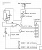
(*correction that this is a 2200 mAh schematic)
First, an explanation -
I wanted to make my first mod a VV that I designed (of course with much inspiration here). I am still new at the more subtle arts of the electronics design (hats off to the masters...this is intense stuff).
I am having issues calculating what POT to use and a couple of the resistors needed to make this what I want.
Before you freak out on me...the Auto mode looks like an always on! It is! The switch is added post atty connector, so in auto mode the atty connector should always have power.
The design should allow the following features:
3.2-6+v to the atty (even a 6 volt top cap is fine for me)
Auto or manual (the auto adapter is tested already and works beautifully up to 6v and I will post once this schematic is done, including how to make the auto adapter)
SEALED 510 connector (the auto adapter makes this possible)
LCD display should output batt voltage (combined) AND if no atty attached, the direct power going to it, with atty it should show under load voltage while vaping.
Mega hours of vaping!
Here is the Schema:

I will attach this in post 2. If there is a major mistake please dont take my head off. I am willing to admit that there is limited knowledge on my part and bow in amazement that alot of you can do this stuff with little to no thought whatsoever. I have been repairing by replacement for years, so soldering/desoldering is not new to me.
My main issue is of course experience and mathmatics (I am learning just not fast enough for the timeframe I want).
I really need help with resistors (labeled R1-R2) and the POT to get the voltage correct. I will be ordering parts hopefully mid next week so I can build this for vapefest Vegas.
The adjustible regulator is from MV (as well as most of the other parts like the LCD) and I would like to keep the cost below 50$ if possible. I will update the schema daily with any changes to keep it current and when I am done I will design a PCB for future use and post it as well (using express PCB). I will upload the Schematic for ExpressSCH if people want me to, just let me know.
Let's see what we can do and hopefully astound vapefesters with a killer VV mod design that will work for everyone. Wouldn't it be nice if there was a 50-60$ mod to handle everyone including auto lovers? (ok, so maybe not everyone, but I bet they would use it if their batt died!
(*correction that this is a 2200 mAh schematic)
First, an explanation -
I wanted to make my first mod a VV that I designed (of course with much inspiration here). I am still new at the more subtle arts of the electronics design (hats off to the masters...this is intense stuff).
I am having issues calculating what POT to use and a couple of the resistors needed to make this what I want.
Before you freak out on me...the Auto mode looks like an always on! It is! The switch is added post atty connector, so in auto mode the atty connector should always have power.
The design should allow the following features:
3.2-6+v to the atty (even a 6 volt top cap is fine for me)
Auto or manual (the auto adapter is tested already and works beautifully up to 6v and I will post once this schematic is done, including how to make the auto adapter)
SEALED 510 connector (the auto adapter makes this possible)
LCD display should output batt voltage (combined) AND if no atty attached, the direct power going to it, with atty it should show under load voltage while vaping.
Mega hours of vaping!
Here is the Schema:
I will attach this in post 2. If there is a major mistake please dont take my head off. I am willing to admit that there is limited knowledge on my part and bow in amazement that alot of you can do this stuff with little to no thought whatsoever. I have been repairing by replacement for years, so soldering/desoldering is not new to me.
My main issue is of course experience and mathmatics (I am learning just not fast enough for the timeframe I want).
I really need help with resistors (labeled R1-R2) and the POT to get the voltage correct. I will be ordering parts hopefully mid next week so I can build this for vapefest Vegas.
The adjustible regulator is from MV (as well as most of the other parts like the LCD) and I would like to keep the cost below 50$ if possible. I will update the schema daily with any changes to keep it current and when I am done I will design a PCB for future use and post it as well (using express PCB). I will upload the Schematic for ExpressSCH if people want me to, just let me know.
Let's see what we can do and hopefully astound vapefesters with a killer VV mod design that will work for everyone. Wouldn't it be nice if there was a 50-60$ mod to handle everyone including auto lovers? (ok, so maybe not everyone, but I bet they would use it if their batt died!
Last edited: