Homemade USB Passthrough (m401).

Status
Not open for further replies.

Zep--

Senior Member
ECF Veteran
Mar 21, 2009
198
0
SW Florida
I used vice grips on the battery tube, and needle nose vice grips on the tiny gold band on the connector, then I just twisted and pulled a bit (10 seconds worth) and it came right off.

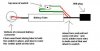
The m401/402 connector does not seem to be glued in, the lower end of the connector (the part in the tube) is serrated and it's more of a pressure fit, other connectors seem to be glued in and heating them up a bit loosens them up.

Zep--
 

Zep--

Senior Member
ECF Veteran
Mar 21, 2009
198
0
SW Florida
Typically, 2 of the wires are "data" wires to transfer information to and from the computer, and the other 2 wires are the Positive and Negative for the power.

When I did it, to be sure before soldering, i just touched 1 wire to the center post of the atomizer (the bottom, not the wick end) then tried the other 3 on the side, when I did red and black that way, the atomizer started glowing (give it a second to fire up), so I knew I had the right wires.

I'd reccomend getting a powered usb hub to avoid blowing up your computer while experimenting. You don't need the hub connected to the computer to use the usb passthru.

Zep--
 

Onthespot

Full Member
Mar 29, 2009
5
0
Typically, 2 of the wires are "data" wires to transfer information to and from the computer, and the other 2 wires are the Positive and Negative for the power.

When I did it, to be sure before soldering, i just touched 1 wire to the center post of the atomizer (the bottom, not the wick end) then tried the other 3 on the side, when I did red and black that way, the atomizer started glowing (give it a second to fire up), so I knew I had the right wires.

I'd reccomend getting a powered usb hub to avoid blowing up your computer while experimenting. You don't need the hub connected to the computer to use the usb passthru.

Zep--
Will try that now, Do you have a diagram of your mod?
 

Zep--

Senior Member
ECF Veteran
Mar 21, 2009
198
0
SW Florida

Attachments

  • homemadepassdiagram.jpg
    homemadepassdiagram.jpg
    18.9 KB · Views: 166
Last edited:

Txrider

Senior Member
ECF Veteran
Apr 3, 2009
176
86
I still don't understand why the included pressure switch in the M401 doesn't seem to play a part in this mod. Can you spell it out for me? :confused:

Because they didnt want it that way.

Sounds like it would be quite simple to just open up the LED end and if two of the wires are + and _ to the battery, just connect up the red/black USB wires, heat shrink wrap it and your done, using the batteries internal pressure switch. I'll likely try it soon enough.
 

Fox3

Senior Member
ECF Veteran
Mar 24, 2009
281
1
Seattle, WA
I was worried about those too when I first built my USBPTs. They do seem to work just fine (going on a couple months now). Recovered those from scrap printed circuit boards.

My homebrews were 801s and I just drilled a hole in the battery body and trimmed the push part of the switch down to where it would just slide into the battery tube. Once positioned under the hole, I push a length of Q-Tip shaft under it and super glue it in position.

Woiks :).
 

Adeem

Senior Member
ECF Veteran
May 20, 2009
111
1
...
I'm trying to make one using the existing (microphone) switch. Took of the LED, took out the battery. I'm assuming the 2 wires coming up are + and - and are coming from the switch. One's black and the other is blue. Does anyone know which one I should attach to the black wire in the USB cable? Is it black to black? Please help. (This is the first time I'm trying anything like this...)
Thanks
 

Adeem

Senior Member
ECF Veteran
May 20, 2009
111
1
...
Sounds like it would be quite simple to just open up the LED end and if two of the wires are + and _ to the battery, just connect up the red/black USB wires, heat shrink wrap it and your done, using the batteries internal pressure switch. I'll likely try it soon enough.
Did you do it? I'd like to try it (as per my post above) and any help would be appreciated.
 

emus

Vaping Master
ECF Veteran
Jun 9, 2009
4,804
2,007
I'm trying to make one using the existing (microphone) switch. Took of the LED, took out the battery. I'm assuming the 2 wires coming up are + and - and are coming from the switch. One's black and the other is blue. Does anyone know which one I should attach to the black wire in the USB cable? Is it black to black? Please help. (This is the first time I'm trying anything like this...)
Thanks

The battery housing is negative.
 
Last edited:

emus

Vaping Master
ECF Veteran
Jun 9, 2009
4,804
2,007
So a 50ma switch should ok on a 500ma USB power?

Zep--

A 50ma switch is rated to reliably handle currents up to 50ma.
I use a 3000ma microswitch and 1500ma power supply on my passthru which produces tons of vapor.
I have seen reports of 50ma switches working fine.
Lucky the 50ma can't talk, I'm sure it would complain.
Your PC will like the 50ma switch because the switches lower current capacity means the PC will not have to work as hard.
 
Last edited:
Status
Not open for further replies.

Users who are viewing this thread