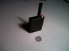
This is a great way to make a 5 Volt Thanks Ez Duzit.
I do have mine working but wanted to find out if possible
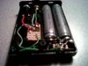
Can anyone tell me what the resister placed here is for?
"While the epoxy sets on the battery contacts, you can solder the resistor into place. Pictures 20 & 21 each show different angles, so you can get the best view. I stripped about ½ inch from a small piece of black wire, and then cut that insulation to proper length to fit over the exposed leg of the resistor. The resistor gets one leg soldered to the control pin, which is row 4, and the other leg is soldered to ground, which is row 3 of the pcb. Make sure you are keeping the correct orientation of the pins, (1,2,3,4), and not reversing them. (Each pin corresponds to the same row, ie, pin 1 is row 1, pin 2 is row 2, etc I numbered the pins in Pic 21 to help prevent mistakes. So be aware of the pin orientation."
This step is located right above Pic 20
I made this diagram here. When I had some trouble only to find out the 2nd pin solder needed redone and it started working.
http://i809.photobucket.com/albums/...od Wire layouts/5VOLTREGULATORWITHBATTS-1.jpg
But raised the question I now seek in this thread.
http://www.e-cigarette-forum.com/forum/madvapes/75979-5-volt-mod.html#post1127407
Could be the resister is for LED? Or is it just required for some other reason I`m not aware of?
Thanks for any feedback to this question.")
I do have mine working but wanted to find out if possible
Can anyone tell me what the resister placed here is for?
"While the epoxy sets on the battery contacts, you can solder the resistor into place. Pictures 20 & 21 each show different angles, so you can get the best view. I stripped about ½ inch from a small piece of black wire, and then cut that insulation to proper length to fit over the exposed leg of the resistor. The resistor gets one leg soldered to the control pin, which is row 4, and the other leg is soldered to ground, which is row 3 of the pcb. Make sure you are keeping the correct orientation of the pins, (1,2,3,4), and not reversing them. (Each pin corresponds to the same row, ie, pin 1 is row 1, pin 2 is row 2, etc I numbered the pins in Pic 21 to help prevent mistakes. So be aware of the pin orientation."
This step is located right above Pic 20
I made this diagram here. When I had some trouble only to find out the 2nd pin solder needed redone and it started working.
http://i809.photobucket.com/albums/...od Wire layouts/5VOLTREGULATORWITHBATTS-1.jpg
But raised the question I now seek in this thread.
http://www.e-cigarette-forum.com/forum/madvapes/75979-5-volt-mod.html#post1127407
Could be the resister is for LED? Or is it just required for some other reason I`m not aware of?
Thanks for any feedback to this question.