
I'm re-posting the tutorial found at the end of the following thread, to give it some more visibility to those who may be interested in it. http://www.e-cigarette-forum.com/forum/battery-mods/97743-what-ti-voltage-regulator-use-5v-mod.html
***Please read the whole tutorial before beginning***
Also read up and watch a video of how to solder if you are new/less then proficient at soldering. Since this is a mock build, I am not trimming down my leads or isolating the heat-sink of the Regulator (the metal tab with the screw hole in it), you will want to do both of these things to prevent headaches later. trim down the metal pins to what you need, wrap them up individually and also heat-shrink or electrical tape the back and metallic sides of the regulator to prevent short circuits.
#1

Tools you'll need:
Wire cutters
Pliers/Multi-tool
Soldering Iron + Solder
Optional tool:
Helping Hands
Components:
Voltage regulator
Momentary switch (SPST) 3 amp 125v
Wire
Lithium batteries ( I use only protected 14500)
Electrical Tape
Optional Components:
Light Emitting Diode (LED)
Printed Circuit Board (PCB)
Optional RECOMMENDED
Master ON/OFF switch
Heat-shrink Tubing
#2
OK... Lets get started. Place Heat-shrink tubing on each wire prior to making a solder connection, or Electrical tape them well.

#3
Pin polarity/function on the TI REGULATOR

#4
(+) Voltage in, left most on a right-side-up Regulator with pins facing you.

#5
(-) Ground, Middle Pin

#6
(+) Voltage out, Right-most pin with Regulator facing up, pins facing down.

#7
How it looks wired up without an LED, If you are using an led, there should be one more ground (middle pin) and one more voltage out, (right pin).

#8
If you are using a battery box with a master on/off switch, this is how it should be wired for the (+) voltage in. Note how the (+) Voltage in passes through the momentary switch before entering the regulator

#9
This is how the (-) ground would wire into the master on/off of the battery box. If you are using another enclosure but still want a master on/off to shut down the entire device, solder it between these two wires.

#10
One of the ground wires (-) from the middle pin needs to connect to the battery connector, Note how it is soldered to the OUTSIDE of the connector.

#11
This is a close-up of the (-) ground wire soldered in #10

#12
This is a the (+ )voltage out.

#13
Close up of #12, note how it attaches to the center of the battery connector Make sure it DOESN'T touch the side or you will have a short circuit

#14
If you are not using an LED, skip to #17 to check your wiring before testing your new PV.
Optional LED polarity, I didn't cut the LED leads down for this instructional, but you will want to trim them down. Keep the long end slightly longer so you can tell which is which. The LED will only function if the polarity is correct. It is important to shrink wrap or electrical tape the leads to the LED, failure to do so will result in a short circuit if and when they do touch.

#15
Connect the additional wire you added to the (-) ground in step #7 to the SHORT (-) end of the LED

#16
Connect the additional wire you added to the (+) Voltage out in step #7 to the long end of the LED.

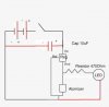
#17
This is how everything should connect together. Make sure you trace out each wire and make sure your optional Master On/off switch is in the on position before test firing your new PV.
CONGRATS AND ENJOY, -DEE

***Please read the whole tutorial before beginning***
Also read up and watch a video of how to solder if you are new/less then proficient at soldering. Since this is a mock build, I am not trimming down my leads or isolating the heat-sink of the Regulator (the metal tab with the screw hole in it), you will want to do both of these things to prevent headaches later. trim down the metal pins to what you need, wrap them up individually and also heat-shrink or electrical tape the back and metallic sides of the regulator to prevent short circuits.
#1
Tools you'll need:
Wire cutters
Pliers/Multi-tool
Soldering Iron + Solder
Optional tool:
Helping Hands
Components:
Voltage regulator
Momentary switch (SPST) 3 amp 125v
Wire
Lithium batteries ( I use only protected 14500)
Electrical Tape
Optional Components:
Light Emitting Diode (LED)
Printed Circuit Board (PCB)
Optional RECOMMENDED
Master ON/OFF switch
Heat-shrink Tubing
#2
OK... Lets get started. Place Heat-shrink tubing on each wire prior to making a solder connection, or Electrical tape them well.
#3
Pin polarity/function on the TI REGULATOR
#4
(+) Voltage in, left most on a right-side-up Regulator with pins facing you.
#5
(-) Ground, Middle Pin
#6
(+) Voltage out, Right-most pin with Regulator facing up, pins facing down.
#7
How it looks wired up without an LED, If you are using an led, there should be one more ground (middle pin) and one more voltage out, (right pin).
#8
If you are using a battery box with a master on/off switch, this is how it should be wired for the (+) voltage in. Note how the (+) Voltage in passes through the momentary switch before entering the regulator
#9
This is how the (-) ground would wire into the master on/off of the battery box. If you are using another enclosure but still want a master on/off to shut down the entire device, solder it between these two wires.
#10
One of the ground wires (-) from the middle pin needs to connect to the battery connector, Note how it is soldered to the OUTSIDE of the connector.
#11
This is a close-up of the (-) ground wire soldered in #10
#12
This is a the (+ )voltage out.
#13
Close up of #12, note how it attaches to the center of the battery connector Make sure it DOESN'T touch the side or you will have a short circuit
#14
If you are not using an LED, skip to #17 to check your wiring before testing your new PV.
Optional LED polarity, I didn't cut the LED leads down for this instructional, but you will want to trim them down. Keep the long end slightly longer so you can tell which is which. The LED will only function if the polarity is correct. It is important to shrink wrap or electrical tape the leads to the LED, failure to do so will result in a short circuit if and when they do touch.
#15
Connect the additional wire you added to the (-) ground in step #7 to the SHORT (-) end of the LED
#16
Connect the additional wire you added to the (+) Voltage out in step #7 to the long end of the LED.
#17
This is how everything should connect together. Make sure you trace out each wire and make sure your optional Master On/off switch is in the on position before test firing your new PV.
CONGRATS AND ENJOY, -DEE


")