You are using an out of date browser. It may not display this or other websites correctly.
You should upgrade or use an alternative browser.
You should upgrade or use an alternative browser.
Mod not working why?
- Thread starter Polatmax
- Start date
- th_trl_thread_readers 0
- Status
- Not open for further replies.
Most of us in this forum would need to do a bit of research on that chip. You could probably get a better answer by posting to the VV/VW forum VV/VW APV Discussion
I'm not a scientist but following the route of electronical flow, it would appear that the switch is being by-passed by having a 510/switch + wire.
Probly better to wait for a nexpert though.
Probly better to wait for a nexpert though.
Providing your wiring is correct, all solder joints are good and the switch actually works I would guess you have a faulty mosfet. Did you buy it from a supplier like Digikey or Mouser? There are a lot of defective and fake components floating around eBay that people will sell.
Also what battery are you using and what build are you putting on this mod? It is possible you don't have enough voltage to turn the mosfet on completely.
Also what battery are you using and what build are you putting on this mod? It is possible you don't have enough voltage to turn the mosfet on completely.
Well... judging from your other posts you have a lack of electronic knowledge. So I would suggest you might be better off with a commercial mod instead of something DIY and dangerous.
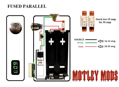
That wiring diagram does not look correct. I will admit, I am only a slightly experienced boat electrician, I basically just used to do what the real electrician told me, but that diagram just doesn't look right to me.
It's the wiring for an N Channel Mosfet, what doesn't appear correct?That wiring diagram does not look correct. I will admit, I am only a slightly experienced boat electrician, I basically just used to do what the real electrician told me, but that diagram just doesn't look right to me.
For one thing, it doesn't look right that there's a 15Kohm load between hot and ground.
Similar to the post by @ppeeble. The same wire to one side of the switch and one side of the 510. I am a fairly experienced computerguy, and just have a basic DC knowledge, and I'm not sure at all (yet.. irlb3034pbf at DuckDuckGo) how that chip works, the diagram just doesn't look right to me. Just mywhat doesn't appear correct?
 , and maybe not worth a grain of salt.
The resistor makes sure that the mosfet turns off since the gate is left floating once you release the switch.For one thing, it doesn't look right that there's a 15Kohm load between hot and ground.
OK. I don't know anything about the transistor (or field effect device, if you prefer) itself, but for some reason, I was thinking that the load should be bigger than that.
I still think that he should just get a decent mech, one without a MOSFET. If you want the protection that a MOSFET provides, better to just stick with regulated.
I still think that he should just get a decent mech, one without a MOSFET. If you want the protection that a MOSFET provides, better to just stick with regulated.
The diagram is correct. Is this a metal box or plastic?
The N Channel mosfet used in that circuit switches the negative wire. The positive from the battery goes directly to the 510 post and a secondary wire to pull the gate high.Similar to the post by @ppeeble. The same wire to one side of the switch and one side of the 510. I am a fairly experienced computerguy, and just have a basic DC knowledge, and I'm not sure at all (yet.. irlb3034pbf at DuckDuckGo) how that chip works, the diagram just doesn't look right to me. Just my, and maybe not worth a grain of salt.
Think of the Mosfet as a relay, with the negative side of the circuit going through the contacts. The positive wire tap only energizes the relays coil.
If it's the same box from his other post, it's 3D printed.The diagram is correct. Is this a metal box or plastic?
I suggest putting heat shrink around it as the tab needs to be isolated and I always fuse the pos from the battery to the 510 just in case. Its cheap and easy to do
His post in the other thread had a no mosfet and a 2A switch between the battery and 510...I suggest putting heat shrink around it as the tab needs to be isolated and I always fuse the pos from the battery to the 510 just in case. Its cheap and easy to do
Those are the ones in the news later. I saw one once where a guy used a mosfet but didnt have a soldering iron so he just twisted the wire around it and used black tapeHis post in the other thread had a no mosfet and a 2A switch between the battery and 510...
I see. Thanks.Think of the Mosfet as a relay, with the negative side of the circuit going through the contacts. The positive wire tap only energizes the relays coil.
The diagram is indeed correct. Problem is, without seeing what you have done, it is impossible to comment on where you have gone wrong. I’d suggest putting a picture up as a starting point.
- Status
- Not open for further replies.
Similar threads
- Replies
- 20
- Views
- 1K
- Replies
- 12
- Views
- 1K
Users who are viewing this thread
Total: 2 (members: 0, guests: 2)

