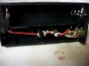
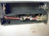
Hey guys this is my first ever mod. I got it all put together and the LED lights up when the button is pressed, but soon as i screw in an atty it all turns off  heres a couple pics. it goes positive from the on/off switch, to the switch, then resistor to the LED to the positive wire to the center of the 510 battery connector. Then the negative LED to the outside of the batt connector, soldered to the negative wire. bleh i suck at soldering right now, so please bare with me


heres a couple pics. it goes positive from the on/off switch, to the switch, then resistor to the LED to the positive wire to the center of the 510 battery connector. Then the negative LED to the outside of the batt connector, soldered to the negative wire. bleh i suck at soldering right now, so please bare with me