my vv booster altoids tin

Status
Not open for further replies.

tmassey

Senior Member
ECF Veteran
Aug 31, 2012
133
61
texas
i spent almost a month on ecf browsing to learn how to build it and im finally done. i told myself i would post a how to on it and here it is. far far from step by step but its most of what you need to know to build one yourself.
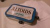
you will need an altoids tin (obviously) an 18650 battery i use the trustfire 3000 mah from madvapes
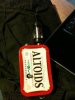
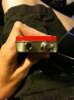
a momentary switch i bought the metal horn switch and the voltage reader from madvapes
an atty lug i used one of the 510 connectors from avidvapes the kind that screw on. i think theres a link in mamu's dena how to
an 18650 battery box i bought 5 from ebay only to find they were too small so i just cut them in half and used 2 positive sides to save space.
then the rest can be bought from mouser
100k potentiometer part : p160kn-0q15b100k
2 16 v dc 100 uf capacitors part: eeu-fr1c101
1/8 watt 15k ohms part: cmf5015k000fhek
1/8 watt 4.7k ohms part:cmf504k7000fkre
booster chip part: ptn04050cad

Untitled.jpg
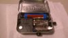
the picture above shows how it is all wired up, i made this for people like me who cant read wiring diagrams. i found it way easier to solder a single wire lead to pins 1 2 and 4 so you can make your connections where there is space rather than soldering each individual connection to the pin, plus you will run out of space quickly especially on the ground pin.

i hope you like it and i hope this helps anyone looking to make a 3.7-6 volt vv booster. pics of it are attached, at least i think
 

Attachments

  • IMG_0551.jpg
    IMG_0551.jpg
    22 KB · Views: 139
  • IMG_0552.jpg
    IMG_0552.jpg
    23.9 KB · Views: 179
  • IMG_0553.jpg
    IMG_0553.jpg
    21.2 KB · Views: 150
  • IMG_0555.jpg
    IMG_0555.jpg
    22.6 KB · Views: 152

Mrgreen819

Senior Member
ECF Veteran
Verified Member
Jun 29, 2012
207
68
North Carolina
Nice efficient regulator, great choice for a boost mod. The 04050 is a switching regulator, it has a stable output which is why it reads well on a standard voltage display. The only device I have seen that uses PWM is the Vmax. There could be more ,there is always something new coming out it seems. Nice job on your first mod you are now hooked!
 

tmassey

Senior Member
ECF Veteran
Aug 31, 2012
133
61
texas
its not my first but its the first that i can say wasnt puck inspired. this one was pretty much just my version of breaktru's .44 mini mod he so kindly posted...and many pointers on how he built it. had to have the 18650's though the lava tube completely spoiled me, i dont use it much now though im pretty sure this puts out a good deal more volts under load than the good ol lava tube does might be just me though and i have no real way to test it
 

Commie

Ultra Member
ECF Veteran
Verified Member
Mar 28, 2012
1,427
2,012
Michigan
Very nice! I think I'll go with your diagram rather than breakthru's. I like you you managed to organize it without the madvapes' PCB. I think this setup has potential to be even more compact than the original .44 mod, and that's saying a lot.

Now I'll have to try to integrate my stupid recessed tanks into that with an altoids tin :)

Must have recessed tank
 

tmassey

Senior Member
ECF Veteran
Aug 31, 2012
133
61
texas
TrustFire Protected 18650 Battery, 3000mAh is the battery im using its not imr and so far so good and i really dont know the answer to the second one i know ti.com has the data sheet but i really dont know the answer
i actully just tried an imr battery and got far far less voltage drop under load. previously i couldnt go above 5.4 volts or so under load but got 6.3. but i was using like 6 dimes as spacers since b/c of the size of my 3000's. bad bad idea LOTS and LOTS of heat and some smoke,will be soldering a spring on it soon luckily it didnt fry the whole thing. but what i saw is enough evidence to say that yes you should use imr's in these if you want to run them at their max which in mine was right around 12 watts
 

Commie

Ultra Member
ECF Veteran
Verified Member
Mar 28, 2012
1,427
2,012
Michigan
Very nice! I think I'll go with your diagram rather than breakthru's. I like you you managed to organize it without the madvapes' PCB. I think this setup has potential to be even more compact than the original .44 mod, and that's saying a lot.

Now I'll have to try to integrate my stupid recessed tanks into that with an altoids tin :)

Must have recessed tank

Yay! Mine is done too. Unfortunately, I had to outfancy you, and added a touch switch there. Works great, until I start mixing my juice, and get my fingers wet with it. Then I end up having to clean the switch, since it stops working.
 

Attachments

  • IMAG0156_sm.jpg
    IMAG0156_sm.jpg
    20.7 KB · Views: 63
  • IMAG0155_sm.jpg
    IMAG0155_sm.jpg
    21.2 KB · Views: 48

Tourlounette

Senior Member
ECF Veteran
Aug 28, 2011
239
288
Montréal
...
then the rest can be bought from mouser
100k potentiometer part : p160kn-0q15b100k
2 16 v dc 100 uf capacitors part: eeu-fr1c101
1/8 watt 15k ohms part: cmf5015k000fhek
1/8 watt 4.7k ohms part:cmf504k7000fkre
booster chip part:
...
to make a 3.7-6 volt vv booster. pics of it are attached, at least i think

Nice job!
I saw you use a 15k ohms between pin 3 and 4 instead the 100k ohms suggest by Breaktru.
What is the difference of using one and the other?
Does it affect the range of voltage?
Thks
 

WillyB

Vaping Master
ECF Veteran
Oct 21, 2009
3,709
591
USA
Two quick questions, since I'm collecting parts to do the exact same
1. Will the battery be ok, without being IMR?
2. Is this booster using pulse width modulation?
I take it you missed this from the datasheet?

Buck_boost_-_1.jpg


Nice efficient regulator, great choice for a boost mod. The 04050 is a switching regulator, it has a stable output which is why it reads well on a standard voltage display. The only device I have seen that uses PWM is the Vmax.
How about the ProVari?

From ProVape's FAQ

Does the ProVari use PWM? (pulse-width modulation)

Yes, the ProVari is using PWM technology

More.

Switching to high efficiency

LDO linear regulators are impressive devices, but sometimes efficiency (and/or the requirement to boost or invert a voltage) is more important than simplicity and cost. And that’s the time to consider a switching DC-to-DC regulator.

A switching DC-to-DC regulator employs a MOSFET in conjunction with a pulse width modulation (PWM) controller, and an inductor and output capacitor forming an L-C filter. The input voltage is connected to the MOSFET, which is switched according to the duty cycle (MOSFET ‘on’ time divided by total period) of the PWM controller. Switching frequencies range from a few kilohertz to several megahertz.
Power converters stretch battery budget | Electronics News

That said the various efficient switching assemblies that modders use from TI, Murata, Dimension Engineering etc, have been properly designed to provide a flat and accurate DC output, not be be confused with the China PVs crude implementation.
 

tmassey

Senior Member
ECF Veteran
Aug 31, 2012
133
61
texas
im actually pretty sure u were lookin at breaktru's old diagram which he used a diode b/c i definetely followed the new diagram. it uses a 100 k pot so i guess either way its probably close to the same resistance. but that could be completely wrong the only way i could have done this was by staring at break's diagrams for hours i know nothing about electronics lol but still enjoy making them.

and that looks really really good commie. thanks for showin me makes mine look pretty noobish lol with all the extra stuff you crammed in yours and still have space. you think there is enough space for all the boost components a pot. screen and parallel 18650's i kill my 1600 mah's in a work day to where it wont put out over 5v .
 

Commie

Ultra Member
ECF Veteran
Verified Member
Mar 28, 2012
1,427
2,012
Michigan
im actually pretty sure u were lookin at breaktru's old diagram which he used a diode b/c i definetely followed the new diagram. it uses a 100 k pot so i guess either way its probably close to the same resistance. but that could be completely wrong the only way i could have done this was by staring at break's diagrams for hours i know nothing about electronics lol but still enjoy making them.

and that looks really really good commie. thanks for showin me makes mine look pretty noobish lol with all the extra stuff you crammed in yours and still have space. you think there is enough space for all the boost components a pot. screen and parallel 18650's i kill my 1600 mah's in a work day to where it wont put out over 5v .

The space is there so you can grab onto the tank to screw/unscrew it. Cramming it all in was a bit challenging, especially the big on-off switch I had there. Therein lies a problem. I used a slightly wrong resistor there and covered it with epoxy :( Now the touch switch doesn't work very well. But the design should be solid, I'm still a huge proponent of encasing the tank, even though it limits your options of tanks that fit.
 

tmassey

Senior Member
ECF Veteran
Aug 31, 2012
133
61
texas
you should get one of those tanks with the little filling hole near the top on the side with a little bolt that keeps it from leaking. cuz it looks like its probably a pain to get that tank out. if it had a filling hole in it you would only have to take it out when changing attys or cartos. sucks about your touch switch. ive now learned maybe i shouldnt use so much epoxy and hot glue...im just waiting for something to mess up in mine, then i get to carve out about a stick of hot glue:mad:
 

Commie

Ultra Member
ECF Veteran
Verified Member
Mar 28, 2012
1,427
2,012
Michigan
you should get one of those tanks with the little filling hole near the top on the side with a little bolt that keeps it from leaking. cuz it looks like its probably a pain to get that tank out. if it had a filling hole in it you would only have to take it out when changing attys or cartos. sucks about your touch switch. ive now learned maybe i shouldnt use so much epoxy and hot glue...im just waiting for something to mess up in mine, then i get to carve out about a stick of hot glue:mad:

Thank you :) They are actually very easy to take out. Once the drip tip is out, the tank screws out and come out. I left enough of a gap inside.
 
Status
Not open for further replies.

Users who are viewing this thread