possible to solder leads back on an ego?

Status
Not open for further replies.

silenthunder

Full Member
Verified Member
Aug 22, 2011
29
3
toronto
I will post some pics in a bit when I find my phone. but heres a description.

couple days ago my ego knockoff (from madvapes, think its a smoketech) started doing something odd. button wouldn't light up at all without an atty on it. with an atty on it, it would just flash (afaik it was on full charge when i tried to charge it).

so..... looked around here and on net - read somewhere that maybe ground might not be connected (although i also read if you get any kind of button 'light' then this probably isn't the case)

being the typical mrfixit that i am I tried to take apart

I was less than gentle.

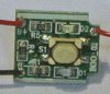
pulled connector out and... basically the situation now is:

the connector (and board) have a black wire attached to it

the battery has a red wire attached to it

(I'm assuming these wires are supposed to also be attached to their counterpart on the tube and board, respectively)

don't think the ground is the problem - I tried to lift the battery out of the tube and it seems to 'stick' after pulled a little distance (so i assume that means the ground at the bottom is still intact)


SOOOO...... my question is: is it possible to solder these wires back on their respective places? I'm gonna order a replacement battery - but if this is fixable I would like to do it and have as a backup.
 

Rocketman

Ultra Member
ECF Veteran
May 3, 2009
2,649
977
SouthEastern Louisiana
When you get it all fixed you will have a PV wilh a loose and weak 'nose' end to point at your face while vaping.

The negative wire goes from the bottom of the cell to the bottom cap and to the board. The positive goes from the cell to a point on the lower end of the board across from the negative. A short wire goes from the top of the board to the connector center pin. If both cells wires came loose from the board you can ohm out the two board connections. The switch is wired to the negative.

The USB or the Upgrade eGo-C have a positive wire that also goes to circuitry in the bottom.
 

SunRam

Senior Member
ECF Veteran
Verified Member
Feb 3, 2012
125
28
South Africa
When you get it all fixed you will have a PV wilh a loose and weak 'nose' end to point at your face while vaping.

The negative wire goes from the bottom of the cell to the bottom cap and to the board. The positive goes from the cell to a point on the lower end of the board across from the negative. A short wire goes from the top of the board to the connector center pin. If both cells wires came loose from the board you can ohm out the two board connections. The switch is wired to the negative.

The USB or the Upgrade eGo-C have a positive wire that also goes to circuitry in the bottom.

Hey Rocketman,

Can you help me.

I have a Joyetech Ego C upgrade passthrough battery, that started blinking when activating the battery. It would work randomly, and other times, just blink a couple of times.

I dissembled mine, and this is what I got now:

View attachment 125105

View attachment 125106

Can you tell me which wire to solder back where?

Right now, this is my last battery and it stopped working - I'm in dire straights right now!

Thanks
 

Rocketman

Ultra Member
ECF Veteran
May 3, 2009
2,649
977
SouthEastern Louisiana
I can't see your photos. But Maybe I can describe where the leads go.

The center pin connects to a plated through eyelet (probably filled with a broken lead now :)) at the front of the board near the center. Close examination will find the spot. as far as the battery leads ( at opposite corners at the bottom of the board), the Negative can be ohmed out. The switch grounds a pin of the controller chip so one lead of the switch will go to ground at one lower corner of the board. The positive connects to the opposite lower corner.

http://www.sulit.com.ph/index.php/v...go+E-Cigarettes+Manual+Batteries#imageGallery


I've got one somewhere but can't find it :)
 
Last edited:

SunRam

Senior Member
ECF Veteran
Verified Member
Feb 3, 2012
125
28
South Africa
Thanks Rocketman,

20120811_214456_1.jpg

Looking at the images in the link you supplied, am I then right to say, black to the top of my picture and red to the bottom, opposite to the way it is in my picture?

My red wire is still connected from the centre pin, to the pcb! Yeah!

BTW what do you mean the Negative can be ohmed out?
 
Last edited:

Rocketman

Ultra Member
ECF Veteran
May 3, 2009
2,649
977
SouthEastern Louisiana
I dug around and found one of my eGo boards :)

Here is a pic of the wires attached. One terminal of the switch has a circuit run that goes to the same spot as the black wire, ground. If you look real close you can see it under the coatings on the board.
Or you can use an ohmmeter to find the negative side.

Looking at your picture it does look like you have it set backwards. Is that a (+) I see on your board?
 

Attachments

  • EGO-wires.jpg
    EGO-wires.jpg
    10.6 KB · Views: 260
Last edited:
Status
Not open for further replies.

Users who are viewing this thread