Reading resistance in Kanthal wire

Status
Not open for further replies.

buce15

Full Member
Verified Member
Dec 5, 2013
42
16
Boca Raton, FL
Hey guys - got a question I need answered, hoping some of you can help. Hope this is posted in the right spot.

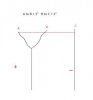
In this highly advanced infographic I've devised, assuming the red horizontal line is a piece of Kanthal (could be anything, I think?) and the positive and negative posts are labeled, would a meter measure the resistance of the wire from A to C or B to C? If you got rid of B, would the reading change? What if A and B were solidly connected, and there was basically a 1" solid connection, no resistance change right? I might have some more follow-up questions, thanks for the help! res2.jpg

p.s. such a dope pic
 

Attachments

  • resistance q.jpg
    resistance q.jpg
    4.2 KB · Views: 46
Last edited:

mujuru

Senior Member
ECF Veteran
Verified Member
Jan 29, 2013
245
229
The O.C.
i'm not electrical expert... but why would you do this in practical application? This would be like basically running one piece of kanthal from positive to positive (which i believe would do nothing) and running another from positive to negative and would be your only active coil.

Seeing that current will take the path of least resistance... My GUESS would be that the readings would simply be the resistance from B to C... even if measured from A to C... to me, power will never pass between A and B as the path of least resistance would always go from B to C. Taking reading from A to C the current would choose not to pass through A to B, but rather jump from A to B via the positive post.. then travel from B to C.

This is all just a logical guess... But nonetheless, i'd just don't see any practical application for running a coil this way. Are you trying to accomplish something in particular?
 

buce15

Full Member
Verified Member
Dec 5, 2013
42
16
Boca Raton, FL
No no, not trying to apply this in any sort of way. I'm basically referring to something much, much smaller than 1", something like 1mm or so. It's a long story really, just trying to understand how meters and mods measure resistance, that's all. I would never attempt to apply something like this.

I guess my biggest question is in the 2nd pic I posted. Would a meter read the resistance from A to C or B to C.

I should prob delete that first pic.
 

buce15

Full Member
Verified Member
Dec 5, 2013
42
16
Boca Raton, FL
Yes the black lines would be directly connected to the meter. Referring to resistance readings, not necessarily electron flow or current flow, but I'm sure those are directly related.

Real world example - just imagine this on a tiny scale. Imperfections in wire, or a screw, any surface. Might only change resistance by .01Ω or less, but would it theoretically change is the question.

Again, I'm just trying to understand what exactly a meter reads as resistance.
 

tokarev

Senior Member
ECF Veteran
Jan 25, 2009
297
473
Tennessee, USA
when using the meter, the battery should be disconnected

so that + and - shouldnt be in the sketch

My thought exactly. The meter supplies the power when measuring resistance. If you put the probes at A and B then you would be measuring the resistance "between" A and B. Same for B and C.

--tokarev
 

edyle

ECF Guru
ECF Veteran
Verified Member
Oct 23, 2013
14,199
7,195
Port-of-Spain, Trinidad & Tobago
Yes the black lines would be directly connected to the meter. Referring to resistance readings, not necessarily electron flow or current flow, but I'm sure those are directly related.

Real world example - just imagine this on a tiny scale. Imperfections in wire, or a screw, any surface. Might only change resistance by .01Ω or less, but would it theoretically change is the question.

Again, I'm just trying to understand what exactly a meter reads as resistance.

If you are putting the probes from the meter onto A and B, then the meter reads the resistance between A and B.

If you are putting the probes from the meter onto A and C, then the meter reads the resistance between A and C, which is going to be about 2 times the resistance between A and B, judging by the sketch.

Someone I don't think that aswers whatever it is you are really trying to ask.
 

edyle

ECF Guru
ECF Veteran
Verified Member
Oct 23, 2013
14,199
7,195
Port-of-Spain, Trinidad & Tobago
The + and - are showing what's connecting to the meter. No battery. I'll keep that in mind next time, thanks.

OH! the + and - are the Probes!!
Ok the the meter measures the resistance between A and C, of course. It can't just magically ignore the length of wire between B and C.

You're trying to understand whether the meter just measures the coil alone or whether it measures everything, aren't ya?
 

buce15

Full Member
Verified Member
Dec 5, 2013
42
16
Boca Raton, FL
Lol we're getting there - the red line is Kanthal. The Black lines are connected to probes. I'm talking about multiple points of contact on a connection.

A and B aren't really the same point. They're on the same connection, they're both part of the positive pin.

Imagine a wire is bent and not securely fastened by a screw. There will be multiple contact points between the wire and the positive connection. Where does the meter read from? The point of the wire that terminated closest to the positive connection (Figure 2, point A), or the point of wire that's closest to the negative connection (Figure 2, point B).

Chances are, we need some sort of electro-genius guy who really knows the answer to chime in on this.

HAAALLLPPPP
 

edyle

ECF Guru
ECF Veteran
Verified Member
Oct 23, 2013
14,199
7,195
Port-of-Spain, Trinidad & Tobago
Lol we're getting there - the red line is Kanthal. The Black lines are connected to probes. I'm talking about multiple points of contact on a connection.

A and B aren't really the same point. They're on the same connection, they're both part of the positive pin.

Imagine a wire is bent and not securely fastened by a screw. There will be multiple contact points between the wire and the positive connection. Where does the meter read from? The point of the wire that terminated closest to the positive connection (Figure 2, point A), or the point of wire that's closest to the negative connection (Figure 2, point B).

Chances are, we need some sort of electro-genius guy who really knows the answer to chime in on this.

HAAALLLPPPP

Many people know the answer. It's the question we're trying to figure out.

You can say the meter reads from the point that one probe touches to the point that the other probe touches.

You can also say the meter reading includes the probes themselves.
 

tokarev

Senior Member
ECF Veteran
Jan 25, 2009
297
473
Tennessee, USA
I'm still not sure if I fully understand the question, but if there are "multiple points of contact" at the positive terminal the meter will read the total resistance between the negative terminal and the closest "point of contact" on the positive terminal. That assumes that you are putting the meter probes on the positive and negative terminals. The terminals can be assumed to have "zero" resistance. Of course all conductors have SOME resistance but in this case it is not measurable by any meter outside of a laboratory. Not one that I can afford anyway.:)
 

twgbonehead

Vaping Master
ECF Veteran
Apr 28, 2011
3,705
7,020
MA, USA
In the diagram, points A and B are shorted together. Therefore, you will measure the resistance from B to C. The section of kanthal from A to B is shorted out by the (very low resistance) meter wire

P.S. I'm not an electro-genius guy, but I faked it pretty well when I was studying EE at MIT ;-)
 
Last edited:
Status
Not open for further replies.

Users who are viewing this thread