On Resistance, Wicking and Contact surface area…
OTA, think it's all about effective wetted contact area. That's the idea behind a t.m.c. If you run a 26awg 9x 2.5mm single at 1Ω then do dual 26's…you're still putting out the same 25W for example (assuming a variable box) across twice the wetted surface. Assuming you have enough wick and enough flow within it you'll double the production (in theory, there are other factors).
You are applying the same power level but doubling the contact area based on the wire's
cross-section. So you're getting more vaporization density (with VW) in this example. Not necessarily a warmer vape (so you would rightly say cooler). But you're using the same power, getting more vape. You've gained effective efficiency of production by design. Go back to the single and your output is less but guess what? It's warmer. Same power.
Thicker wire will draw more power (or needs to be provided proportionately more amps) to achieve a given wattage output. What some refer to as ramp up is simply wire needing time to absorb or move that flow to peak watts. You have to fill the barrel large or small and the latter is easier and faster. Perhaps not the best analogy but simplest for me to compare. So important here is that you're producing more vapor density if enough wick media is there to answer the demand for flow created by that heat.
So then the real question is — what is the maximum vapor density this device can produce?
The vaporization temp for our juices is comparatively low relative to the overall wire temp's being achieved. More actual juice vaporization with the additional effective contact surface should be the goal. And that's my strategy is to find that optimal high side of fit for wire, coil and wick that the device will support. What's the most this baby will do if I floor it? We can always back off from that. But once it's built, that's your limit…not necessarily that of the device. We can always adjust downward if we like. For hotter faster flow with a smaller diameter say; or, wetter, cooler, denser keeping it bigger or fatter.
By definition, No. 36 AWG is 0.005 inches in diameter, and No. 0000 is 0.46 inches in diameter. The ratio of these diameters is 1:92. Six steps down in gauge will get you a roughly halving of cross-section; but four steps down, roughly a quarter of the resistance.
Studying the tables will give you some insights into what power or amps the wire will pull or require to reach a temp or resistance target. Generally lower will use or need more power as resistance lowers. But if/as this translates to more contact surface…and that depends on your design…you will see more actual vapor production. The reverse may be true at the margins. Transition points between wire gauges. So that a small count wind of higher gauge like 25AWG may give better performance than say a high count of 24AWG. Even as the higher mass is lower res and the higher having less turn counts (contact)…
a the higher rate of vaporization can happen if there's more effective contact area relative to resistance.
This is what I suggest bearing in mind, increasing the amount of wire (mass) will not necessarily yield more vapor production. Only what part comes in contact with wetted media. And the more efficient the wind in doing so, the more vaporization you will see. Exposed surface doesn't induce vaporization directly but enhances diffusion of the vapor adding heat in the process. Some swear by this and wind fat. Go back a few years and the trend went to ribbon to achieve the lowest possible aspect ratio (or profile) for the wire relative to the wick. I think this is a very meaningful strategy. We can build a lot of pretty wire but most of it is decoration.
Not an easy subject to grasp. And I claim to be no expert on either resistance or wire. Given my experience tho lots of us are missing out on a fine vape for the lack of just a little better knowledge. Hope you've seen
steam-engine.org because that's going to be your
Rosetta Stone for wading through resistance in the language of numbers. Build a short table for your device at your expected best or preferred resistance. Expand up and down and you might get some surprises.
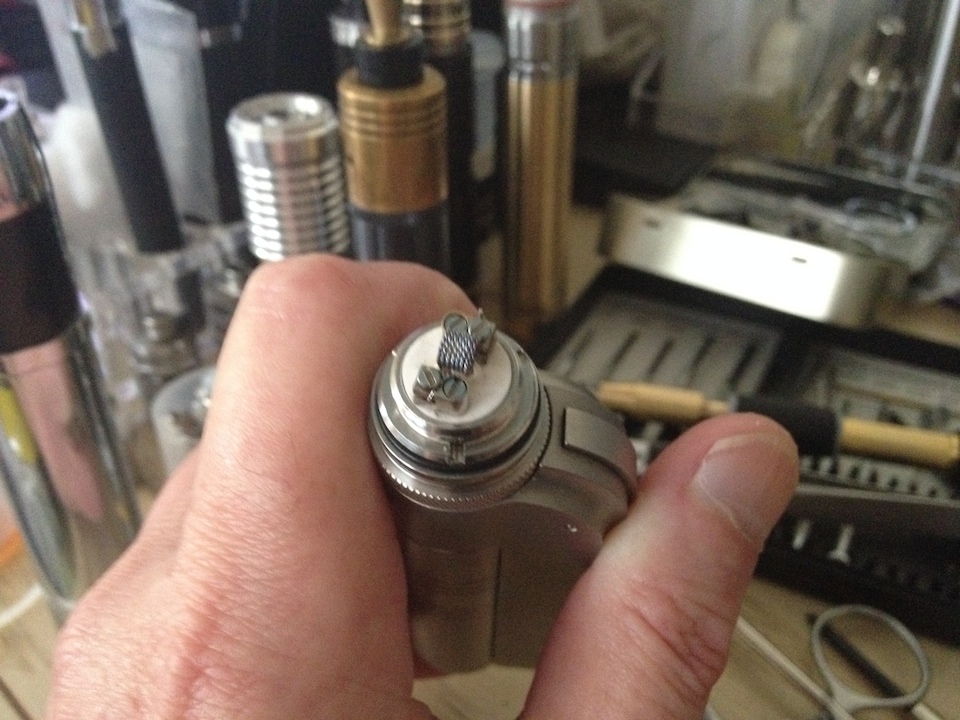
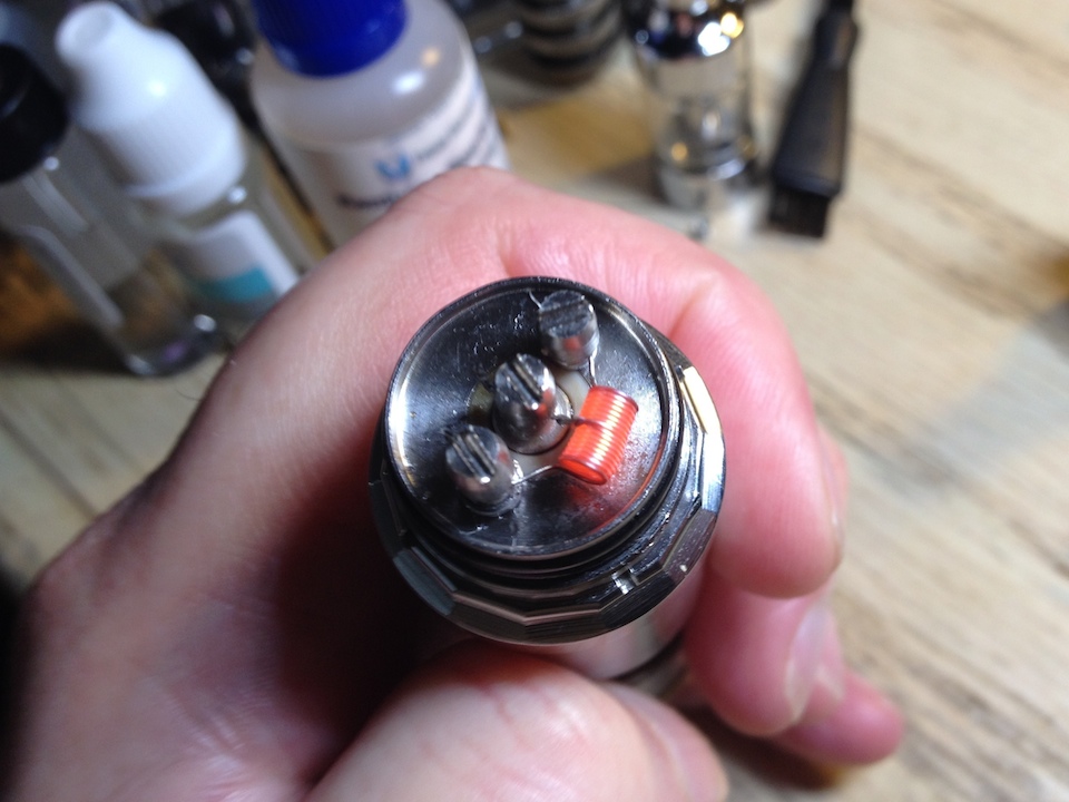
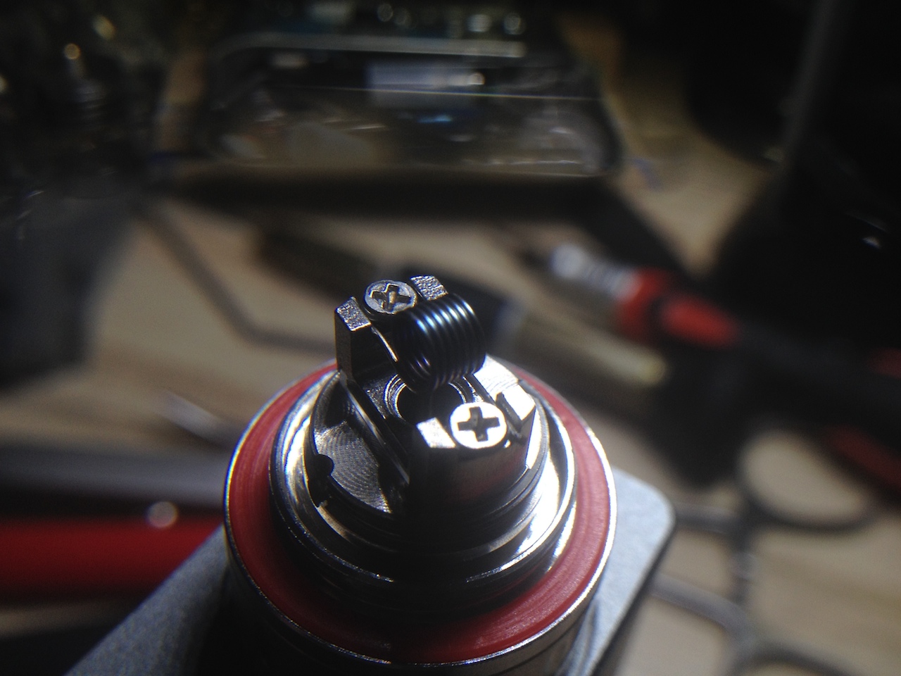
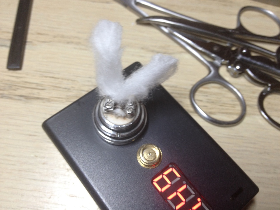
As I write I'm rockin' an original Subtank/RBA/IPV D2 KA1 @20W, 4.2V build using standard single airflow with a 3.2mm Ø t.m.c., looks like this…
25x1 7/7 @ 3.175mmØ t.m.c.= 0.8855Ω
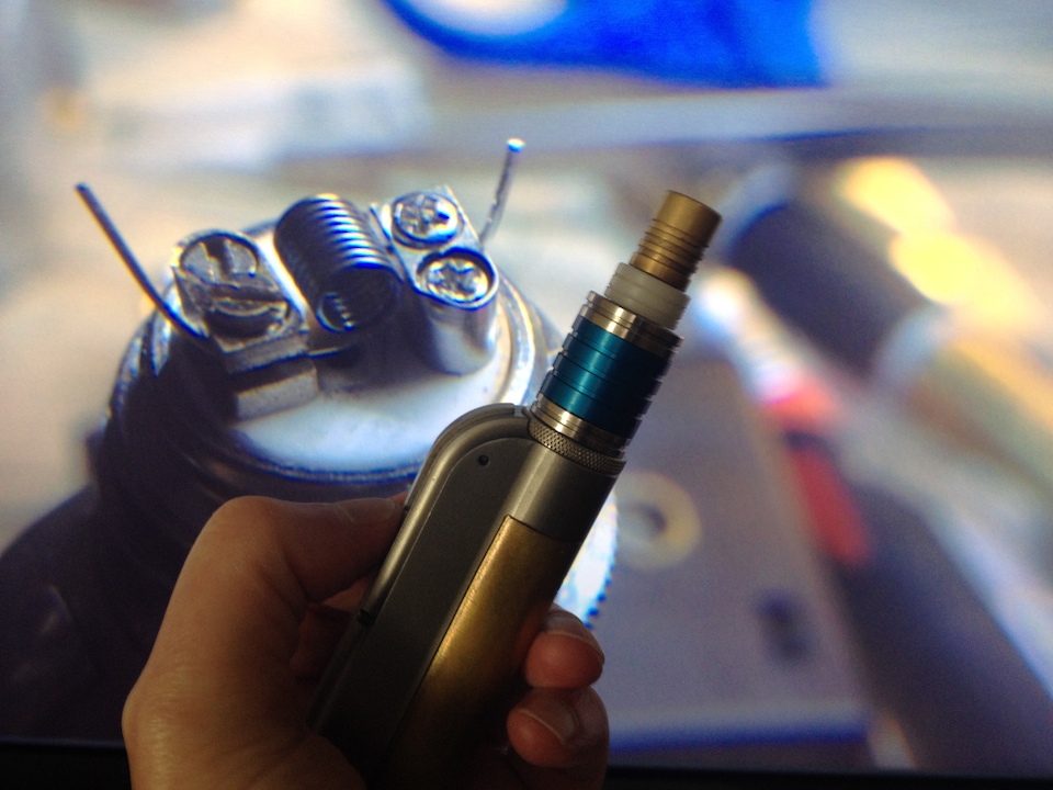
Talkin' shop with a B&M manager few days back vapin' this and this big box vaper thought I was pushin' 50W. To his surprise when I shone the screen. But I've posted pics buried here some place, displaying or not, on my initial high limit tests for the Subtank and it rocked with a t.m.c. even with the stocker RBA deck at the time. This particular RBA has been very slightly drilled out to allow for more wicking (yes, even fatter). But I can take this
median build which is no stress on the batt and easily kick at much higher than normal density beyond 30W…and you guessed it, as you said…it's cool.
Good luck OTA.
")